Automatically Balancing Register for HVAC Systems

a technology of automatic balancing and registers, which is applied in the direction of ventilation systems, heating types, and static/dynamic balance measurement, etc., can solve the problems of rarely achieving a uniform comfort level in the building, manual adjustment registers are difficult to achieve, and the system is difficult to achiev

Active Publication Date: 2010-07-01
ZONER
View PDF53 Cites 302 Cited by
  • Summary
  • Abstract
  • Description
  • Claims
  • Application Information

AI Technical Summary

Problems solved by technology

However, in practice, this seldom works properly.
In addition, it may be impossible to get enough conditioned air to a region without adjusting the registers in every other region.
Thus, manually adjusted registers rarely achieve a uniform comfort level throughout a building.
Manually adjusted registers can also waste energy.
This causes the blower that moves the air to do more work than necessary, thereby wasting energy.
In addition, the high air pressure in the ducts exacerbates any leaks in the ducts.
Such duct leaks frequently allow conditioned air to enter an attic, crawl space or other region that does not need heating or cooling, thereby wasting energy.
Not only does this mean that only one region actually maintains a desired temperature, it also makes it impractical to adjust the temperature in different rooms to suit the needs of occupants in those rooms.
Consequently, room temperatures cannot be personalized.
This is not only expensive; it can also be extremely wasteful of energy.
For example, there is usually nothing to prevent one HVAC zone from heating a portion of a building while another HVAC zone cools another, possibly overlapping, region of the building.
However, such centralized systems require installing wiring to the thermostats, dampers, etc., thereby increasing the difficulty of retrofitting existing buildings.
Furthermore, once such a system is installed, it is difficult to subdivide it into additional zones or to incrementally expand the system.

Method used


Image

  • Automatically Balancing Register for HVAC Systems
  • Automatically Balancing Register for HVAC Systems
  • Automatically Balancing Register for HVAC Systems

Examples


Embodiment Construction

[0067]Definitions. As used in this description and the accompanying claims, the following terms shall have the meanings indicated, unless the context otherwise requires:

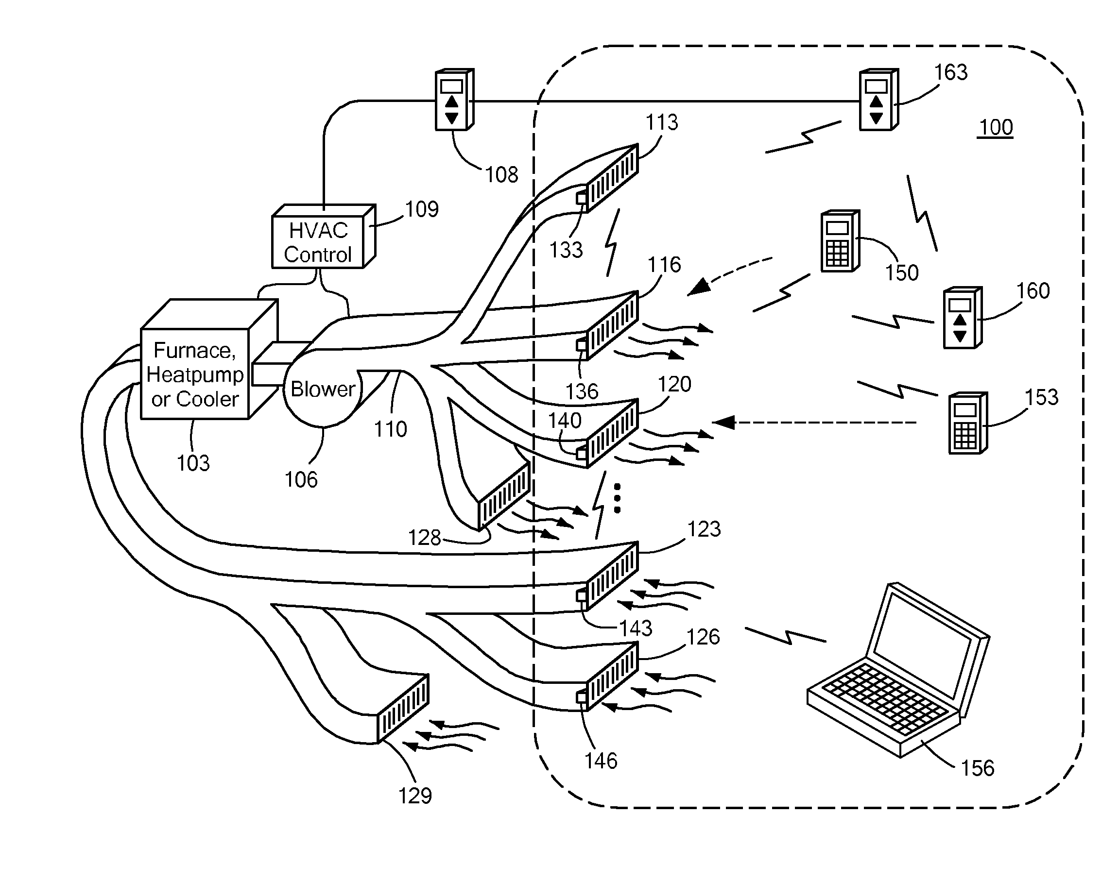
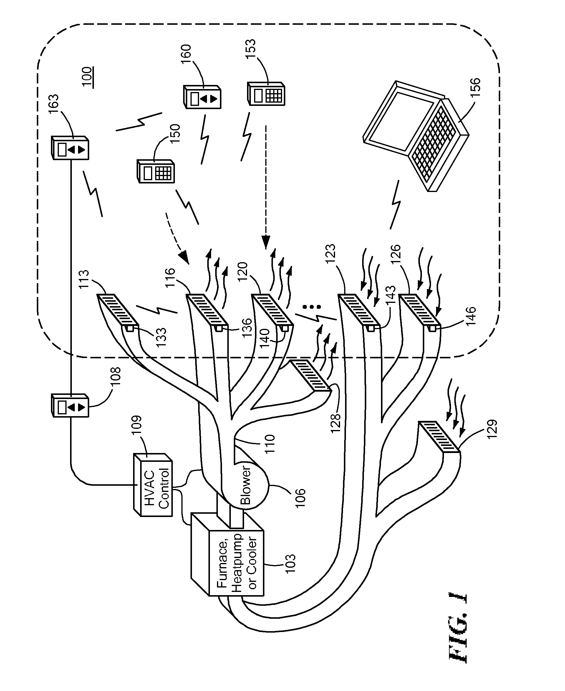
[0068]“HVAC system” means a system that provides heat, ventilation and / or air conditioning to a building or a portion of a building. An HVAC system may provide one or more such functions.

[0069]“Array of photovoltaic cells” means one or more cells that convert light into electricity by the photovoltaic effect.

[0070]“Hydronic” means the use of water as a heat-transfer medium in a HVAC heating or cooling system. Examples of heating systems include steam and hot-water radiators. In large-scale commercial buildings, such as high-rise and campus facilities, a hydronic system may include a chilled water loop and a heated water loop to provide for both heating and air conditioning. Chillers and cooling towers may be used separately or together to provide water cooling, while boilers may be used to heat water.

[0071]A “control...


PUM


Abstract

Distributed nodes, such as intelligent register controllers, of a heating, ventilating and / or air conditioning (HVAC) system wirelessly communicate with each other on a peer-to-peer basis, forming a network, and collectively control the HVAC system, without a central controller. The intelligent register controllers collectively control the amount of conditioned air introduced into each region. Each node may base its operation at least in part on information about one or more (ideally all) of the other nodes. Each intelligent register controller automatically determines how much conditioned air to allow into its region, or how much return air to allow to be withdrawn from its region, based on information collected by the register controller, such as: current temperature of the region; desired temperature of the region; calculated amount of conditioned air required to change the region's temperature to the desired temperature; temperature of conditioned air begin supplied by a duct to the register; current time, day of week, vacation or other schedule data; temperatures of other regions and their respective desired temperatures; calculated amounts of air required to be supplied or withdrawn by the other controlled registers to change their respective regions' temperatures to their desired temperatures; or combinations thereof. Each register controller automatically determines when and to what extent to operate its respective controllable damper.

Description

CROSS REFERENCE TO RELATED APPLICATIONS[0001]This application claims the benefit of U.S. Provisional Patent Application No. 61 / 203,911, filed Dec. 30, 2008 by Jon Barrett and Ronald Lingemann, titled “Automatically Balancing Register for HVAC Systems,” the entire contents of which are hereby incorporated by reference herein, for all purposes.TECHNICAL FIELD[0002]The present invention relates to control systems for heating, ventilating and air conditioning (HVAC) system and, more particularly, to systems that distribute control of an HVAC system among a plurality of components, such as air supply registers, remote control units and thermostats, which communicate with each other.BACKGROUND ART[0003]Conventional forced air heating, ventilating and / or air conditioning (HVAC) systems have manually adjustable air register vents (air volume control dampers) to control the amount of conditioned air introduced into a room or other portion (for simplicity, collectively hereinafter referred to...

Claims


Application Information

Patent Timeline
Patent Type & Authority Applications(United States)
IPC IPC(8): F24F7/00G05B15/00G05D23/00F24F11/76
CPCF24F13/082G05D23/1932F24F3/044F24H9/2064F24F11/76F24F11/755F24F11/30F24F11/62F24F11/56G05D23/1934F24F11/52G05D23/1928
Inventor BARRETT, JONLINGEMANN, RONALD
Owner ZONER
Why Eureka
Try Eureka