Precursors for silicon dioxide gap fill

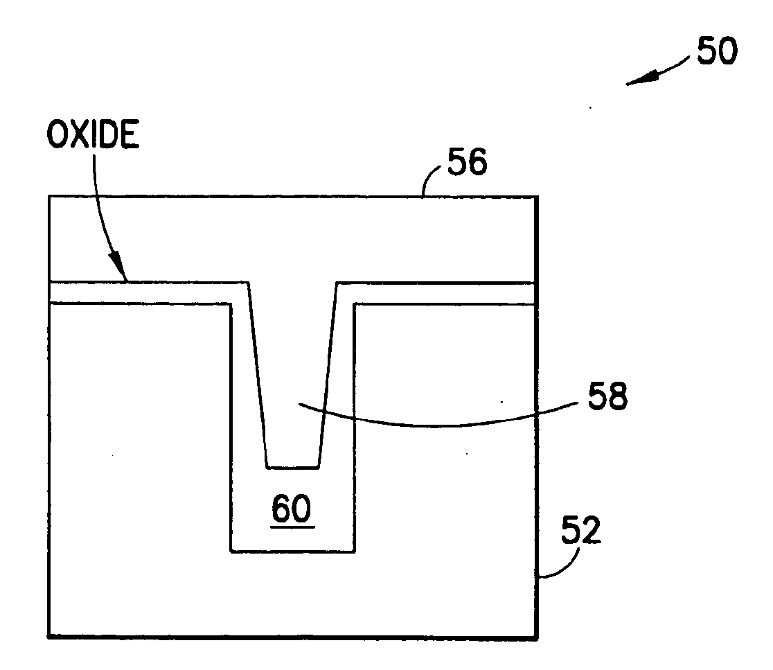
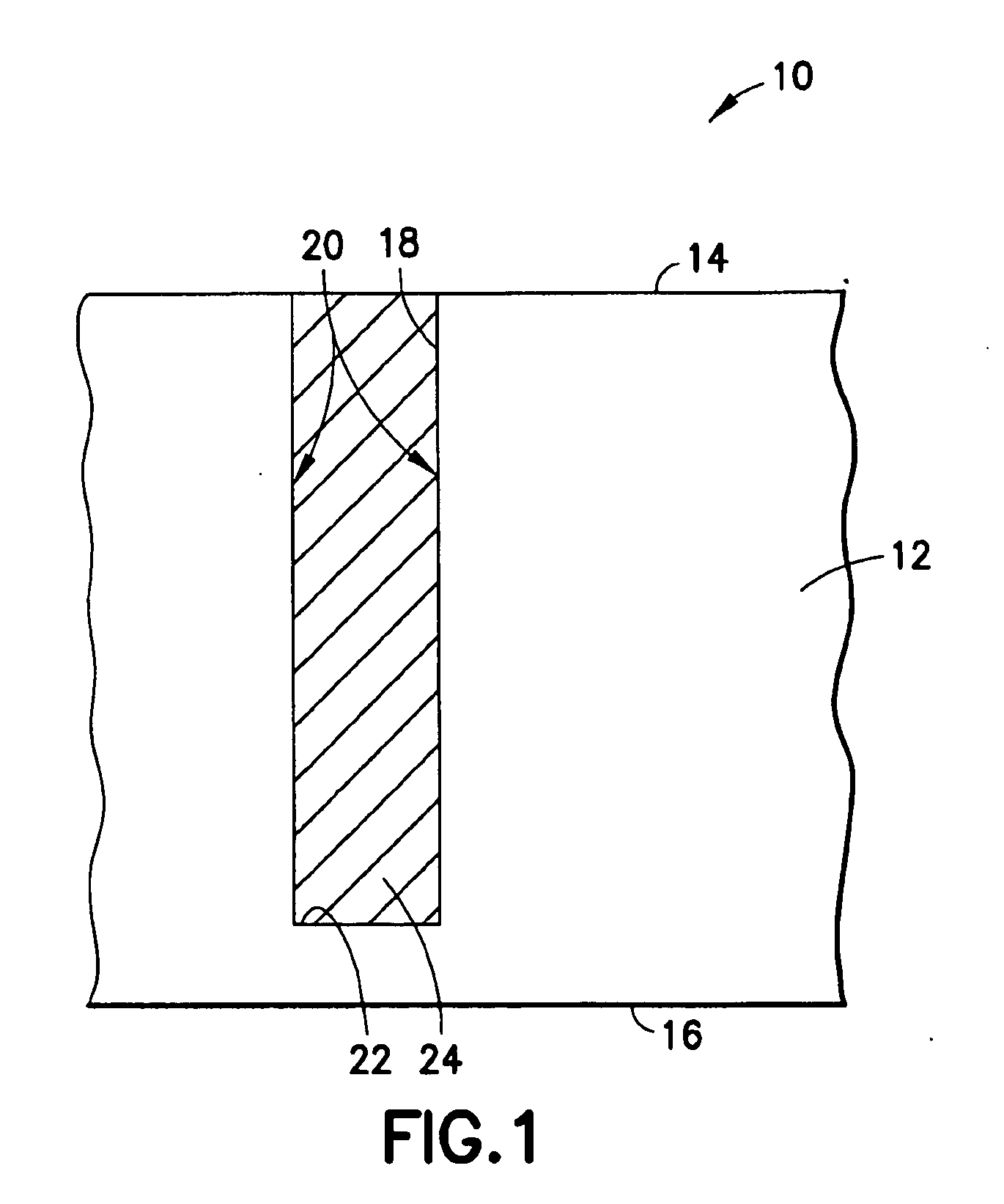
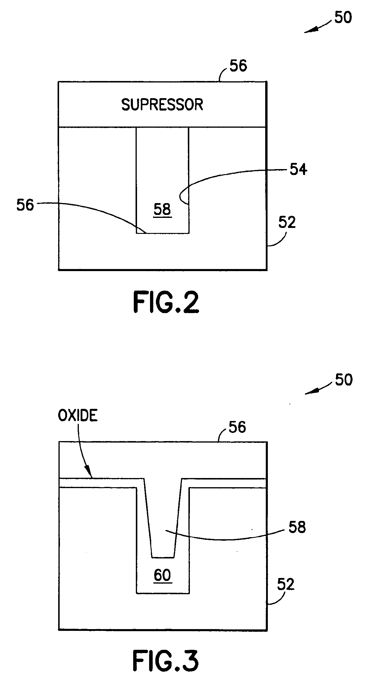
a silicon dioxide and gap filling technology, applied in the direction of coatings, semiconductor devices, chemical vapor deposition coatings, etc., can solve the problems of uneven material densification adversely affecting device performance, and becoming progressively more difficult to deposit silicon dioxide in the narrow trenches without introducing, etc., to achieve the effect of suppressing adverse seam effects

Active Publication Date: 2010-07-01
ENTEGRIS INC
View PDF71 Cites 58 Cited by
  • Summary
  • Abstract
  • Description
  • Claims
  • Application Information

AI Technical Summary

Benefits of technology

[0019]Still another aspect of the invention relates to a method of suppressing adverse seam effects in fill of a trench structure of a substrate

Problems solved by technology

However, with technology nodes decreasing to below 65 nm, it becomes progressively more difficult to deposit silicon dioxide in narrow trenches without introducing voids in the deposited material.
Voids, cracks, and other defects in turn create inhomogenieties in the dielectric material that adversely affect device performance.
Uniform material densification in the narrow trenches is also a problem with conventionally available silicon dioxide precursors due to diffusion-limited oxidation that occurs during their curing.
A low temperature process is preferred, due to high temperature incompatibilities with other structures, materials, and processes in the integrated circuit or memory device that lead to a degraded device with poor performance when high temperature annealing is employed.
Further, high temperature annealing increases the overall thermal budget of the p

Method used


Image

  • Precursors for silicon dioxide gap fill
  • Precursors for silicon dioxide gap fill
  • Precursors for silicon dioxide gap fill

Examples


example 1

[0090]

ParameterValueTEOS firstStabilize in TEOS 90 seconds beforedepositionPressure500TorrSusceptor Temperature425 CFormulation: IPA / Methanol / TEOS4:4:1Liquid Flow0.433 cc / minOzonator feed gas10SLM O2 + 100 ppm N2Ozone Concentration12%Susceptor spacing420 milsVoid % Annealed (800 C 30 min)10.57Void % As deposited6.88Rate4.5 A / sectime for 2000A444 seconds

example 2

[0091]

ParameterValueTEOS firstStabilize in TEOS 90 seconds beforedepositionPressure500TorrSusceptor Temperature425 CFormulation:IPA:Ethanol:TMOG:TEOS0.05:0.10:0.05:1Liquid Flow0.35 cc / minOzonator feed gas10SLM O2 + 100 ppm N2Ozone Concentration15%Susceptor spacing420 milsGe content (film)2 atomic %Void % Annealed (800 C 30 min)3.59%Void % As deposited1.86Rate10 A / sec

example 3

[0092]

ParameterValueTEOS firstStabilize in TEOS 90 seconds beforedepositionPressure500TorrSusceptor Temperature425 CFormulation:IPA:Ethanol:TMOG:TEOS0.05:0.10:0.20:1Liquid Flow0.35 cc / min.Ozonator feed gas10SLM O2 + 100 ppm N2Ozone Conc15%Susceptor spacing420 milsVoid % Annealed (800 C 30 min)1.34%Void % As deposited0.71Rate6 A / sec


PUM

PropertyMeasurementUnit
Temperatureaaaaaaaaaa
Compositionaaaaaaaaaa
Densityaaaaaaaaaa

Abstract

A full fill trench structure comprising a microelectronic device substrate having a high aspect ratio trench therein and a full filled mass of silicon dioxide in the trench, wherein the silicon dioxide is of a substantially void-free character and has a substantially uniform density throughout its bulk mass. A corresponding method of manufacturing a semiconductor product is described, involving use of specific silicon precursor compositions for use in full filling a trench of a microelectronic device substrate, in which the silicon dioxide precursor composition is processed to conduct hydrolysis and condensation reactions for forming the substantially void-free and substantially uniform density silicon dioxide material in the trench. The fill process may be carried out with a precursor fill composition including silicon and germanium, to produce a microelectronic device structure including a GeO2/SiO2 trench fill material. A suppressor component, e.g., methanol, may be employed in the precursor fill composition, to eliminate or minimize seam formation in the cured trench fill material.

Description

CROSS-REFERENCE TO RELATED APPLICATIONS[0001]The present invention claims the benefit of priority under 35 USC 119 of U.S. Provisional Patent Application No. 60 / 946,968 filed Jun. 28, 2007 and U.S. Provisional Patent Application No. 61 / 055,809 filed May 23, 2008. The disclosures of said U.S. Provisional Patent Applications are hereby incorporated herein by reference, in their entireties, for all purposes.FIELD OF THE INVENTION[0002]The present invention relates to trench structures of microelectronic devices and methods for fabricating same, and to precursors having utility for forming silicon dioxide full-fill high aspect ratio trench structures in which the silicon dioxide precursor is flow filled in the trench and cures rapidly at low temperature to form silicon dioxide of a substantially void-free condition with substantially uniform density throughout its bulk volume.DESCRIPTION OF THE RELATED ART[0003]As dimensions in integrated circuits continue to decrease, correspondingly n...

Claims


Application Information

Patent Timeline
IPC IPC(8): H01L29/06C09D7/00H01L21/762
CPCH01L21/02123H01L21/02164H01L21/02263H01L21/31604H01L29/0649H01L21/02211H01L21/02216H01L21/02222H01L21/31608C23C16/42H01L29/76
Inventor HUNKS, WILLIAMXU, CHONGYINGHENDRIX, BRYAN C.ROEDER, JEFFREY F.BILODEAU, STEVEN M.LI, WEIMIN
Owner ENTEGRIS INC
Why Eureka
Try Eureka