Power Converting Apparatus

a power conversion and power technology, applied in the direction of dynamo-electric converter control, motor/generator/converter stopper, dynamo-electric gear control, etc., can solve the problem of generating a big nois

Inactive Publication Date: 2010-07-01
MITSUBISHI ELECTRIC CORP
View PDF2 Cites 18 Cited by
  • Summary
  • Abstract
  • Description
  • Claims
  • Application Information

AI Technical Summary

Benefits of technology

[0007]A power converting apparatus according to the present invention can suppress a torque ripple component equivalent to a sixth-order frequency of an inverter frequency because three pulses in

Problems solved by technology

However, in the above-described conventional inverter modulation method, when the synchronous modulation is performed, especially when the three-pulse synchronous modulation or the single-pulse synchronous modulation at the output voltage being about the terminal voltage is perf

Method used


Image

  • Power Converting Apparatus
  • Power Converting Apparatus
  • Power Converting Apparatus

Examples


Embodiment Construction

[0025]Exemplary embodiments of a power converting apparatus according to the present invention are described in detail below with reference to the accompanying drawings. The present invention is not limited to these exemplary embodiments.

[0026](Structure of Power Converting Apparatus)

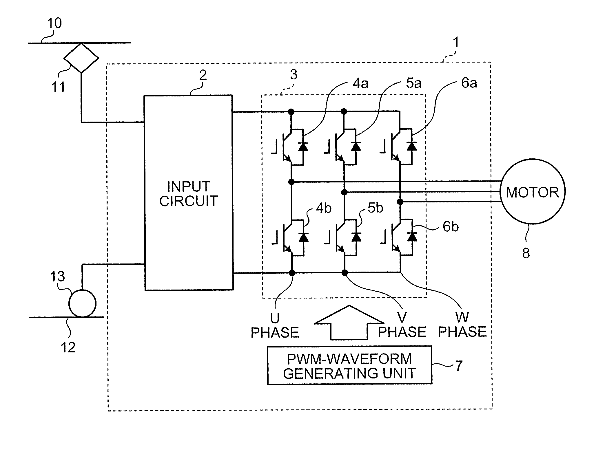
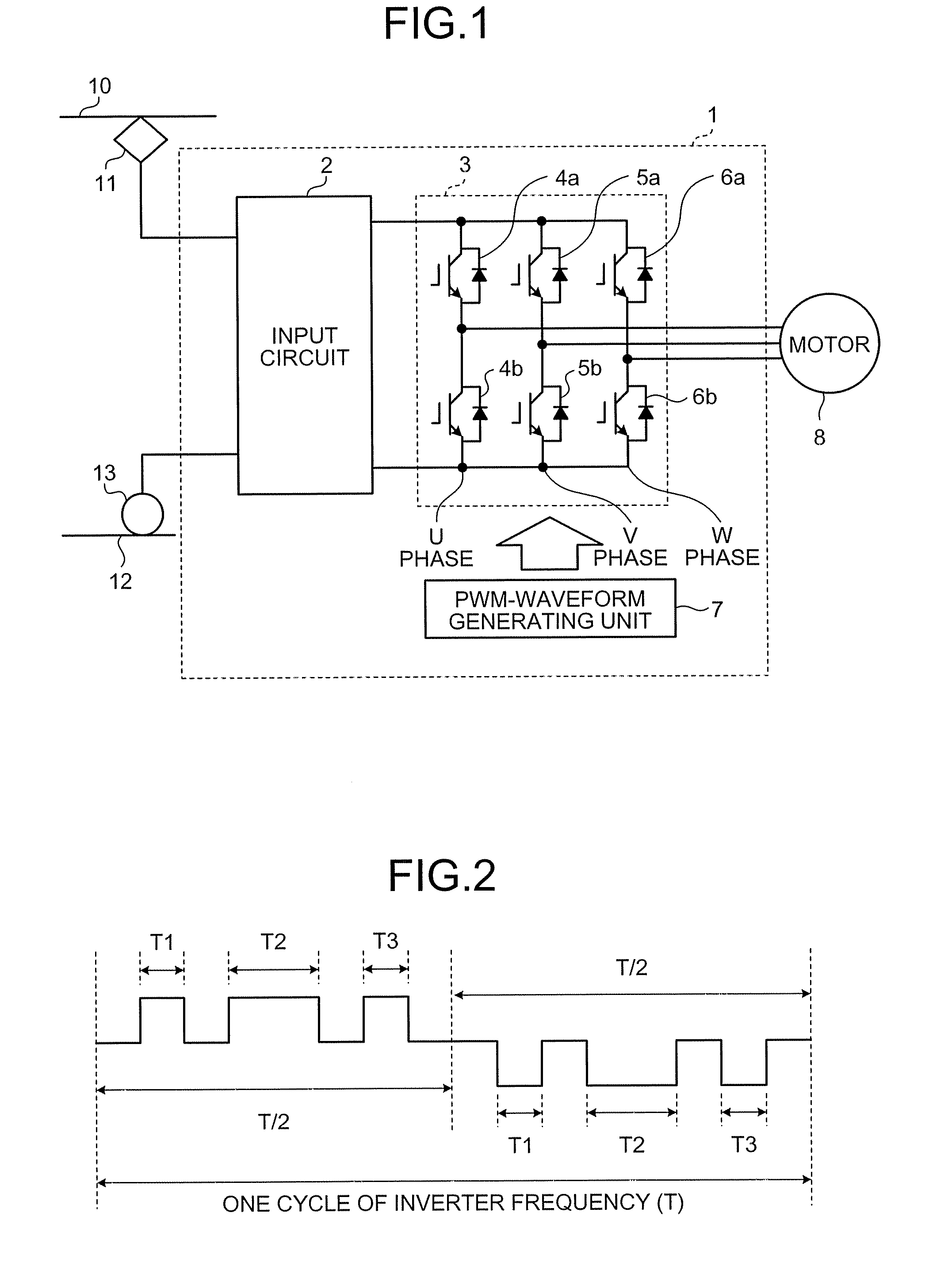
[0027]FIG. 1 is a diagram for explaining a structural example of a power converting apparatus according to an embodiment of the present invention. As shown in the figure, a power converting apparatus 1 of the present embodiment includes an input circuit 2 that at least includes a switch, a filter condenser, and a filter reactor; an inverter unit 3 that includes switching elements 4a, 5a, 6a, 4b, 5b, and 6b, and that is connected to at least one motor 8 for driving an electric locomotive; and a PWM-waveform generating unit 7 that generates and outputs a PWM waveform for controlling switching of the inverter unit 3. An induction motor or a synchronous motor is suitable as the motor 8 connected to the inve...


PUM


Abstract

To reduce, in a power converting apparatus for an electric locomotive, a sixth-order harmonic noise induced by a torque ripple component equivalent to a sixth-order frequency of an inverter frequency. When a motor is driven in a three-pulse mode to drive the electric locomotive, three pulses included within a ½ cycle of the inverter frequency in a PWM waveform, which is used for controlling a switching element of an inverter unit that drives the motor, are set to satisfy Tq≧T/8, Tp≦Tq/2, and Tr≦Tq/2 where, assuming that the three pulses include a first pulse, a second pulse, and a third pulse from an order of generation, Tp is a pulse width of the first pulse, Tq is ½ of a pulse width (full width at half maximum of a pulse) of the second pulse, Tr is a pulse width of the third pulse, and T is a cycle of the inverter frequency.

Description

TECHNICAL FIELD[0001]The present invention relates to a power converting apparatus (inverter) for an electric locomotive, more particularly, to a power converting apparatus capable of effectively reducing sixth-order harmonic noise induced by a harmonic current that is generated when the electric locomotive is driven by inverter modulation method (hereinafter, “sixth-order harmonic noise”).BACKGROUND ART[0002]Non-patent document 1 discloses a conventional inverter modulation method for driving an electric locomotive. In the inverter modulation method disclosed in Non-patent document 1 multi-pulse asynchronous modulation is used when inverter frequency is low, three-pulse synchronous modulation is used when the inverter frequency increases to a predetermined level, and single-pulse synchronous modulation is used when or after the output voltage reaches a termination voltage (rated output: 100%).[0003]Non-patent document 1: “Instruction to inverter-controlled electric locomotive” Hide...

Claims


Application Information

Patent Timeline
IPC IPC(8): H02P6/14H02P21/05H02P23/04H02P23/07H02P25/022H02P27/06H02P27/08
CPCH02J1/102H02J3/38Y04S10/126Y02E60/721H02P27/08Y02E60/00
Inventor HIGUCHI, YUTAKA
Owner MITSUBISHI ELECTRIC CORP
Why Eureka
Try Eureka