
Array of very light readers for active RFID and location applications

a very light reader and active rfid technology, applied in the field of rfid systems, can solve the problems of increasing the cost of the reader further, lowering the coverage ability of the system, and the use of readers usually capable of providing coverage for the size of the facility may still not provide adequate rf coverage, so as to improve the reliability of backhaul, and reduce the probability of collision

Active Publication Date: 2010-07-01
ZEBRA TECH CORP
View PDF21 Cites 9 Cited by
  • Summary
  • Abstract
  • Description
  • Claims
  • Application Information

AI Technical Summary

Benefits of technology

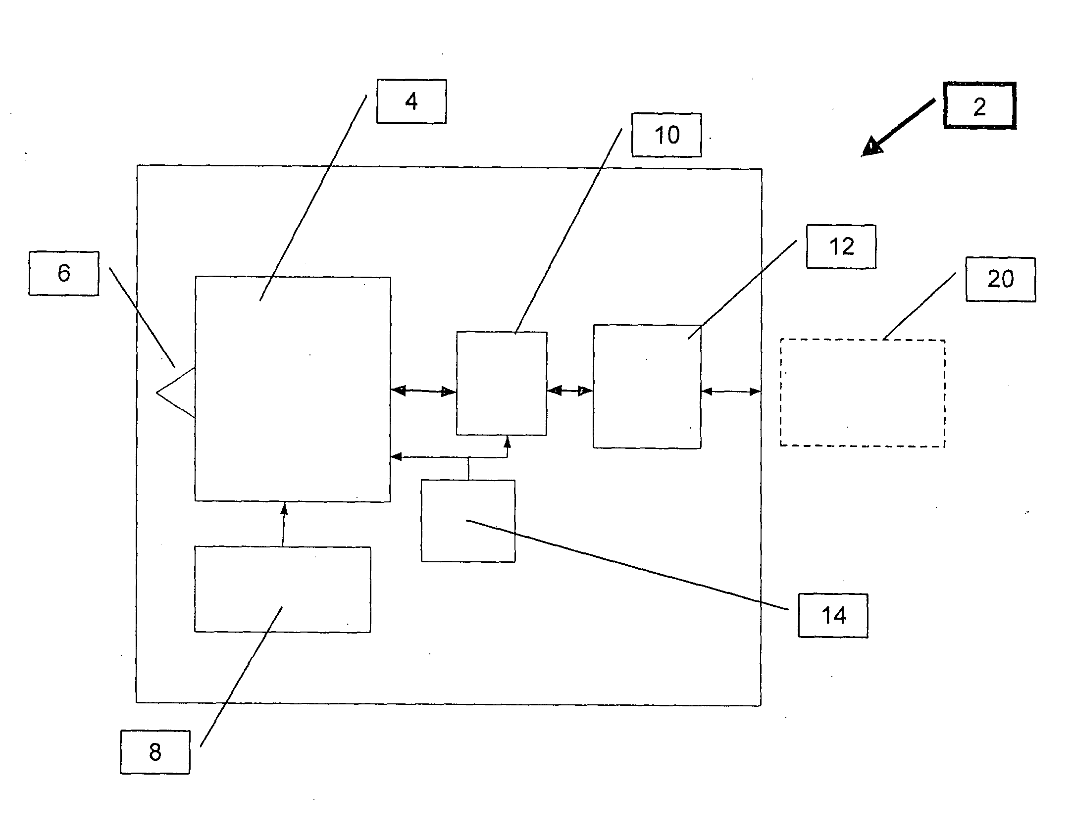
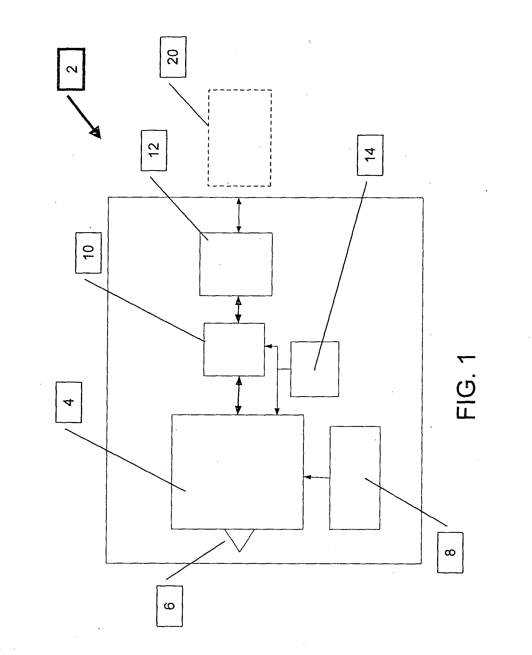
[0013]According to the teachings of the present invention there is provided, a low cost RFID Very Light Reader device comprising: (a) a wide-band Active RFID Tag; (b) a controller configured to implement the Media Access Control (MAC) protocol of the system; and (c) a communication interface subsystem that provides connection to a system network.
[0017]According to a further teaching of the present invention, said base module is configured for interconnection with more than one Tag module so as to increase reception capabilities of the modular wide-band RFID Very Light Reader.
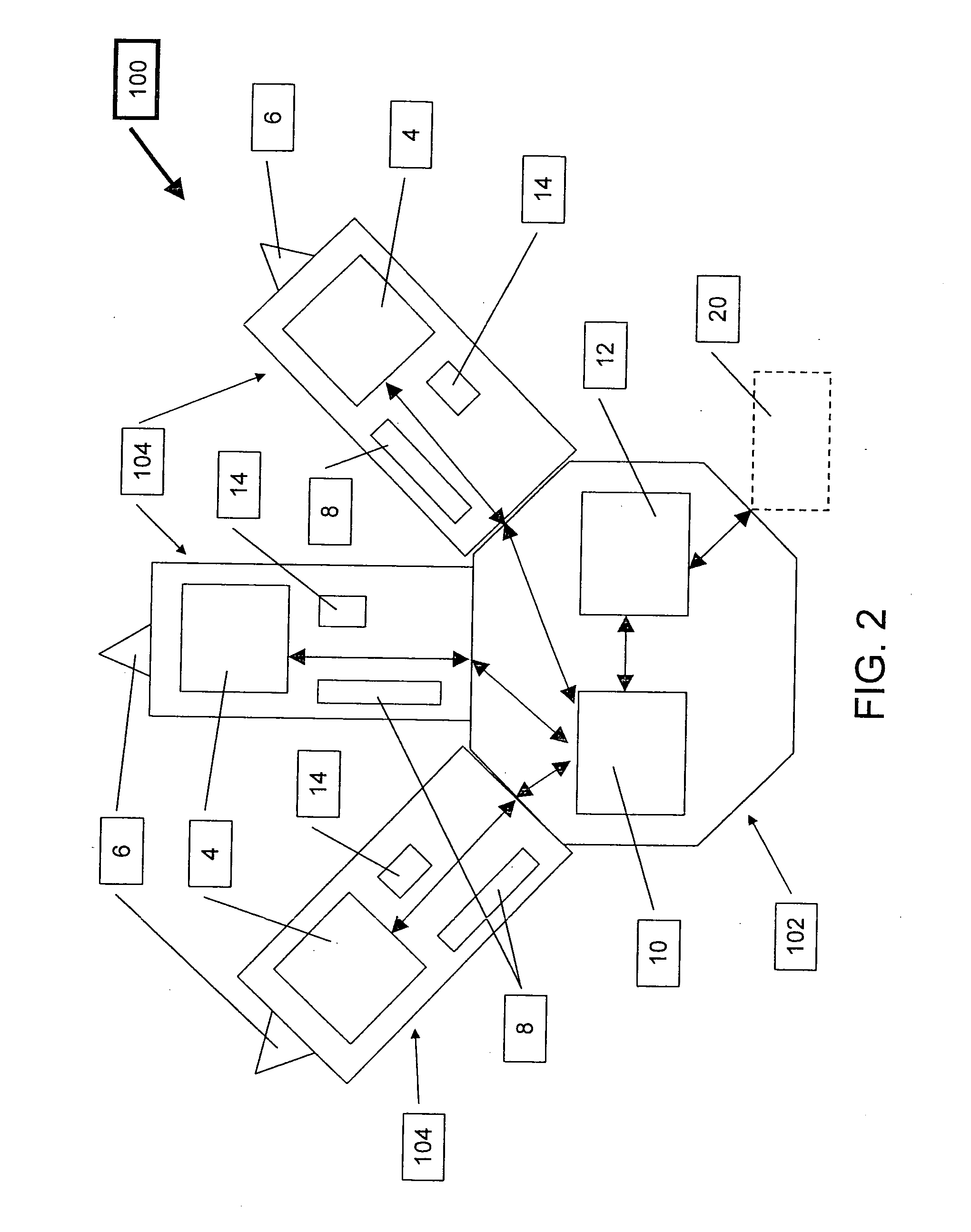
[0021]There is also provided according to the teachings of the present invention, a method for implementing an Active RFID system that employs communication between Readers in order to improve the Backhaul reliability by utilizing reader reception overlap, the method comprising: upon transmission of a packet from a first reader and subsequent reply to the packet from a tag, the reply is received by a second reader, the second reader relays the reply to a system server and informs the first reader of receipt of the reply, whereupon the first reader sends an acknowledgement to the tag.
[0022]There is also provided according to the teachings of the present invention, a method of reducing the collision occurrence in a network for communicating between multiple readers and a plurality of RF tags, the method comprising the steps of: (a) transmission by at least one Reader of at least one wide band interrogation signal; (b) reception of the interrogation signal by at least one Tag; (c) transmission by the Tag of a response signal in response the interrogation signal; (d) reception of the response signal by the Reader; (e) estimation by the Reader as to a quantity of wide band response signals received in response to the interrogation signal; (f) determination by the Reader of a round trip delay time of each the response signal; (g) estimation by the Reader as to whether a collision between a plurality of the wide band response signals occurred and if so, (i) transmission by the Reader of at least one additional wide band interrogation signal, the additional wide band interrogation signal initiating a new communications session between the Reader and the at least one RF Tag in order to reduce the collision probability between the wide band response signals transmitted by the Tags; and (h) transmission by the Reader of an acknowledgment packet to the responding Tag such that, (i) the Tag will not answer again to that broadcast session in case a broadcast command has to be re-transmitted due to an estimation that some collisions occurred during a previous session; and (ii) at least one other such Reader in the network receives the acknowledge packet such that the other Reader will not try again to reach the Tag, thereby lowering congestion directed toward the Tag from multiple Reader transmissions.
[0023]There is also provided according to the teachings of the present invention, a system capable of reducing the collision occurrence in a network for communicating between multiple readers and a plurality of RF tags, the system comprising: (a) at least one Tag configured to receive at least one wide band interrogation signal, transmit a response signal in response the interrogation signal; (b) at least one Reader configured to transmit the interrogation signal and receive the response signal, the Reader further configured to: (i) estimate a quantity of wide band response signals received in response to the interrogation signal; (ii) determine a round trip delay time of each the response signal; (iii) estimate as to whether a collision between a plurality of the wide band response signals occurred and if so, transmit at least one additional wide band interrogation signal, the additional wide band interrogation signal initiating a new communications session between the Reader and the at least one RF Tag in order to reduce the collision probability between the wide band response signals transmitted by the Tags, and (iv) transmit an acknowledgment packet to the responding Tag such that, the responding Tag will not answer again to that broadcast session if a broadcast command is re-transmitted due to an estimation that some collisions occurred during a previous session, and (c) at least a second Reader in the network configured to receive the acknowledge packet such that the second Reader will not try again to reach the Tag, thereby lowering congestion directed toward the Tag from multiple Reader transmissions.

Problems solved by technology

Generally speaking, the prior art Readers are capable devices, but their price and size often require limiting the number deployed in a system in order to maintain a reasonable overall system cost, which in turn lowers the coverage abilities of the system.
The requirement of serving large number of Tags in a large volume thereby requiring coverage of large distances may increase the cost of the Reader further.
If the volume to be covered is divided into a number of sub-volumes such as a large facility with a number of small rooms, by non-limiting example, then the use of Readers usually capable of providing coverage for the size of the facility may still not provide adequate RF coverage due to RF attenuation caused by walls and ceilings.

Method used


Image

  • Array of very light readers for active RFID and location applications
  • Array of very light readers for active RFID and location applications
  • Array of very light readers for active RFID and location applications

Examples


Embodiment Construction

[0031]The present invention is a cost effective system that uses an array of Very Light Readers (VLR's) in which each VLR is based on an augmented RFID Tag circuit.

[0032]The principles and operation of system that uses an array of VLR's according to the present invention may be better understood with reference to the drawings and the accompanying description.

[0033]By way of introduction, the terms “Very Light Reader”, “Very Light Readers”, “VLR” (singular) and “VLR's” (plural) are used herein to refer to an augmented RFID Tag circuit as described herein and such terms may be used interchangeably.

[0034]The VLR's of the present invention provide an alternative to the costly RF Readers of the prior art. The system of the present invention uses a relatively large quantity of VLR's per a given site, providing higher coverage and with a low installation and maintenance cost. In order to reduce the size and cost in comparison to known Readers, the functionality of a VLR is limited.

[0035]Th...


PUM


Abstract

The Very Light Readers of the present invention are based on an augmented Tag circuit with a preferred embodiment including at least one VLSI chip integrating a UWB front end, digital transceiver, and possibly an internal controller; a UWB Antenna; a power supply; a controller configured to implement the Media Access Control protocol of the system; a Communication Interface subsystem for connection to the system network and a clock source. Also described is a system capable of reducing collision occurrence in a network for communicating between multiple readers and a plurality of RF Tags. Tags are configured to receive interrogation signals and transmit response signals. Readers are configured to transmit interrogation signals, receive response signals, estimate the quantity of responses received to an interrogation, determine the round trip delay time of each response and estimates whether a collision between responses has occurred. If so, the Reader transmits an additional interrogation signal. The Reader also transmits an acknowledgment packet to responding Tags so responding Tag will not answer again to that broadcast session. Other Readers in the network also receive the acknowledge packet and do not try again to reach the responding Tags, thereby lowering congestion directed toward Tags from multiple Reader transmissions.

Description

FIELD AND BACKGROUND OF THE INVENTION[0001]The present invention relates to RFID systems and, in particular, it concerns a cost effective system that uses an array of Very Light Readers (VLR's) in which each VLR is based on an augmented RFID Tag circuit.[0002]RF identification (RFID) systems are used to track objects, animals and / or people in a large range of applications. A general term for the application is Asset Management. RFID systems are radio communication systems that communicate between a radio transceiver, called a Reader, and a number of inexpensive devices called Tags. The Reader is also called “Interrogator” in the relevant literature.[0003]An RFID system generally includes multiple Tags which are attached to objects (or assets) being monitored and one or more Readers which are used to communicate with the Tags. An encoder is optionally used to program the Tags with unique identification information.[0004]In some of the RFID applications there is a need for real-time v...

Claims


Application Information

Patent Timeline
Patent Type & Authority Applications(United States)
IPC IPC(8): H04Q5/22
CPCG06K7/10306G06K7/10019H04W74/00G06K7/10356
Inventor RAPHAELI, DANIKAPLAN, GIDEONMENKES, ABRAHAMSELA, GUYMARINOV, IZHARRAM, UZI
Owner ZEBRA TECH CORP
Learn More