Display device and method of driving same

a display device and display device technology, applied in the field of display devices and a method of driving the display device, can solve the problems of slow response speed of lcd, difficulty in increasing the size increasing the depth of the display device, so as to achieve uniform width and different widths

Inactive Publication Date: 2010-07-01
SAMSUNG DISPLAY CO LTD
View PDF5 Cites 9 Cited by
  • Summary
  • Abstract
  • Description
  • Claims
  • Application Information

AI Technical Summary

Benefits of technology

[0012]The microshutter electrodes may be opened and closed through a static electricity force between the microshutter electrodes and the pixel electrode, and an elastic force of the microshutter electrodes. The microshutter electrodes may have different elastic forces. The microshutter electrodes may have a uniform width. The microshutter electrodes may have different widths. The microshutter electrodes may have a high stress portion meeting a portion where they are moved and a portion where they are fixed each other, and the widths of the high stress portions of the microshutter electrodes may be different. An additional film covering the high stress portion may be further included, the microshutter electrodes may have a high stress portion meeting a portion where they are moved and a fixed portion where they are fixed to each other, and the additional film may have different lengths or may be included at a different number per microshutter electrode. The microshutter electrodes may be made of different materials. An additional film covering the microshutter electrode may be further included, and the additional film may have different lengths per microshutter electrode. The static electricity forces between the pixel electrode and the microshutter electrodes may be different from each other. The pixel electrode may include at least two small portions corresponding to the microshutter electrodes and separated from each other by a predetermined interval. A central line of the small portions may accord with a central line of the microshutter electrodes. Overlapping widths between the small portions and the microshutter electrodes may be the same. The overlapping widths between the small portions and the microshutter electrodes may be different from each other. One end of each of the small portions may be connected to each other. A light blocking member blocking light transmitted between the microshutter electrodes may be further included. A thin film transistor electrically connected to the pixel electrode or the microshutter electrodes may be further included. A gate line, a data line, and a switching transistor and a reset transistor, each respectively including a gate electrode, a source electrode, and a drain electrode, may be further included, wherein the gate electrode of the switching transistor may be connected to the corresponding gate line, the source electrode of the switching transistor may be connected to the data line, and the drain electrode of the switching transistor may be connected to the microshutter electrodes. The gate electrode of the reset transistor may be connected to the previous gate line, the source electrode of the reset transistor may be connected to the pixel electrode, and the drain electrode of the reset transistor may be connected to the microshutter electrodes.

Problems solved by technology

The CRT display has a drawback in that as its size increases, its depth also increases, and thus it is difficult to increase the size of the display device.
However, the LCD has a slow response speed, and the PDP has high power consumption.

Method used


Image

  • Display device and method of driving same
  • Display device and method of driving same
  • Display device and method of driving same

Examples


Embodiment Construction

[0028]Embodiments of the present invention will be described more fully hereinafter with reference to the accompanying drawings, in which examples of embodiments of the invention are shown. As those skilled in the art would realize, the described embodiments may be modified in various different ways, all without departing from the spirit or scope of the present invention.

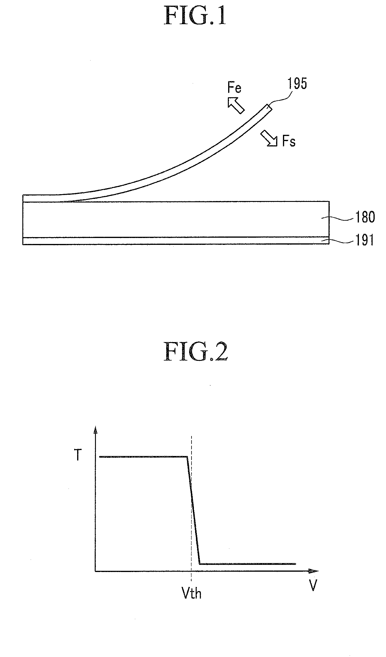
[0029]Firstly, a display device according to an embodiment of the present invention and a curved line of a voltage-transmittance according to an operation of a microshutter electrode will be described with reference to FIG. 1 and FIG. 2. FIG. 1 is a cross-sectional view of a display device according to an embodiment of the present invention, showing operation of a microshutter electrode, and FIG. 2 is a transmittance graph according to voltage applied to a microshutter electrode in accordance with an embodiment.

[0030]A display device may generally be classified into a display panel and a backlight unit (not shown). ...


PUM


Abstract

Embodiments of the present invention operate at least two microshutter electrodes with different voltages from each other for displaying grays. Also, a data voltage is applied to the microshutter electrodes after an initialization voltage when the display device has hysteresis characteristics such that erroneous operation due to the hysteresis characteristics is eliminated. As described herein, the display device including the microshutter electrodes may display subdivided grays.

Description

CROSS-REFERENCE TO RELATED APPLICATIONS[0001]This application claims priority to and the benefit of Korean Patent Application No. 10-2008-0135662 filed in the Korean Intellectual Property Office on Dec. 29, 2008, the entire contents of which are incorporated herein by reference.BACKGROUND[0002]1. Technical Field[0003]Embodiments of the present invention generally relate to a display device and a method of driving the display device. More particularly, embodiments of the present invention relate to a display device and a method of driving it using microshutter electrodes for representing grays.[0004]2. Related Art[0005]Display devices have progressed from the well-known cathode ray tube (CRT) displays to flat panel displays, such as liquid crystal displays (LCDs), plasma display panels (PDPs), and the like. A CRT display displays an image by causing an electron beam to collide with a fluorescent material. The CRT display has a drawback in that as its size increases, its depth also in...

Claims


Application Information

Patent Timeline
Patent Type & Authority Applications(United States)
IPC IPC(8): G06F3/038G02B26/02G09G3/36
CPCG02B26/02G09G3/2011G09G3/346G09G2300/0809G09G2310/0251G02F1/133G02F1/1343G09G3/20G09G3/36
Inventor SHIN, KYOUNG-JUCHAI, CHONG-CHULJO, SEI-HYOUNG
Owner SAMSUNG DISPLAY CO LTD
Why Eureka
Try Eureka