Camera with dynamic calibration and method thereof

a dynamic calibration and camera technology, applied in the field of camera dynamic calibration, can solve the problems of the initial calibration of the camera, and achieve the effects of detecting the range and tracing range of moving objects, and increasing the portability of the application

Inactive Publication Date: 2010-07-01
IND TECH RES INST
View PDF5 Cites 39 Cited by
  • Summary
  • Abstract
  • Description
  • Claims
  • Application Information

AI Technical Summary

Benefits of technology

[0017]In the present invention, a PTZ camera and a point light source projection apparatus are integrated, and the estimation of the dynamic camera calibration parameters is achieved through a motor signal within the PTZ camera and a projection position on the ground projected by the point light source. For the calibrated camera, the time spent for preparing the related calibration images f

Problems solved by technology

First, the camera is subject to an initial calibration.

Method used


Image

  • Camera with dynamic calibration and method thereof
  • Camera with dynamic calibration and method thereof
  • Camera with dynamic calibration and method thereof

Examples


Embodiment Construction

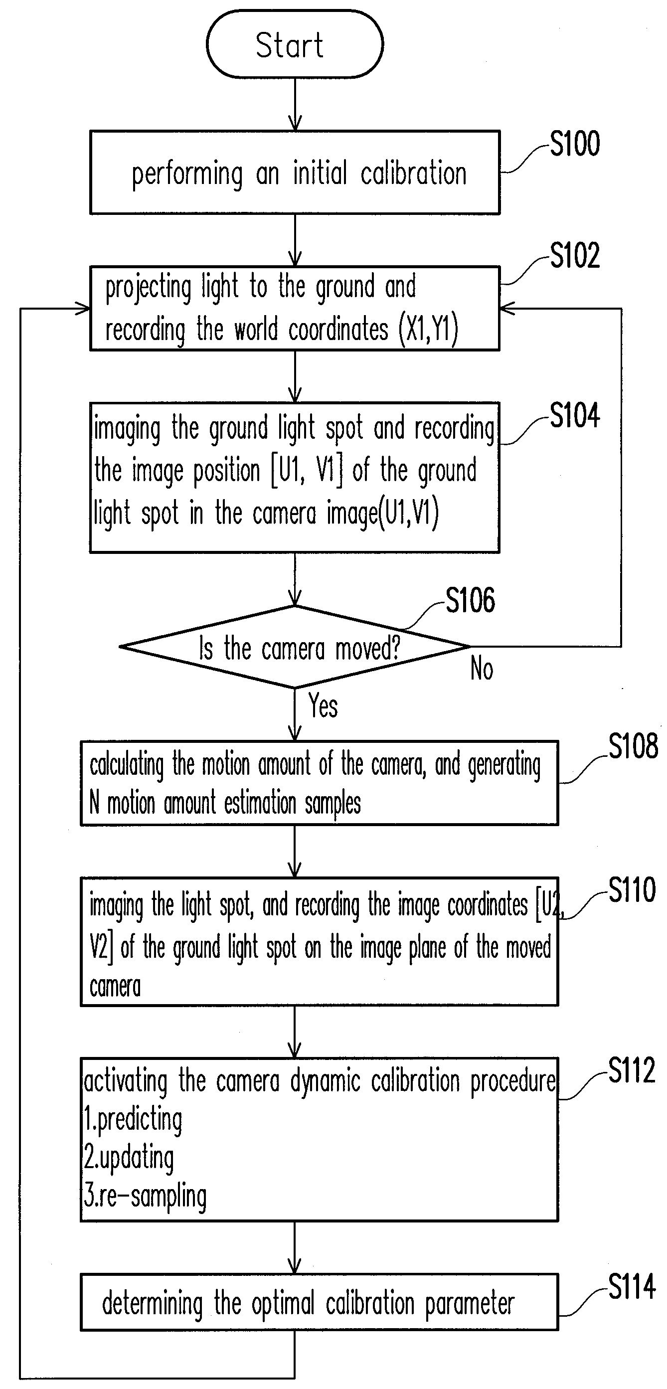
[0026]A sensor integration and a pose estimation techniques used for achieving the present invention can perform an on-line camera calibration by integrating a motor rotation signal of the camera and a light spot projected on the ground by a point light source projection module of the camera. Several embodiments are provided for description as follows.

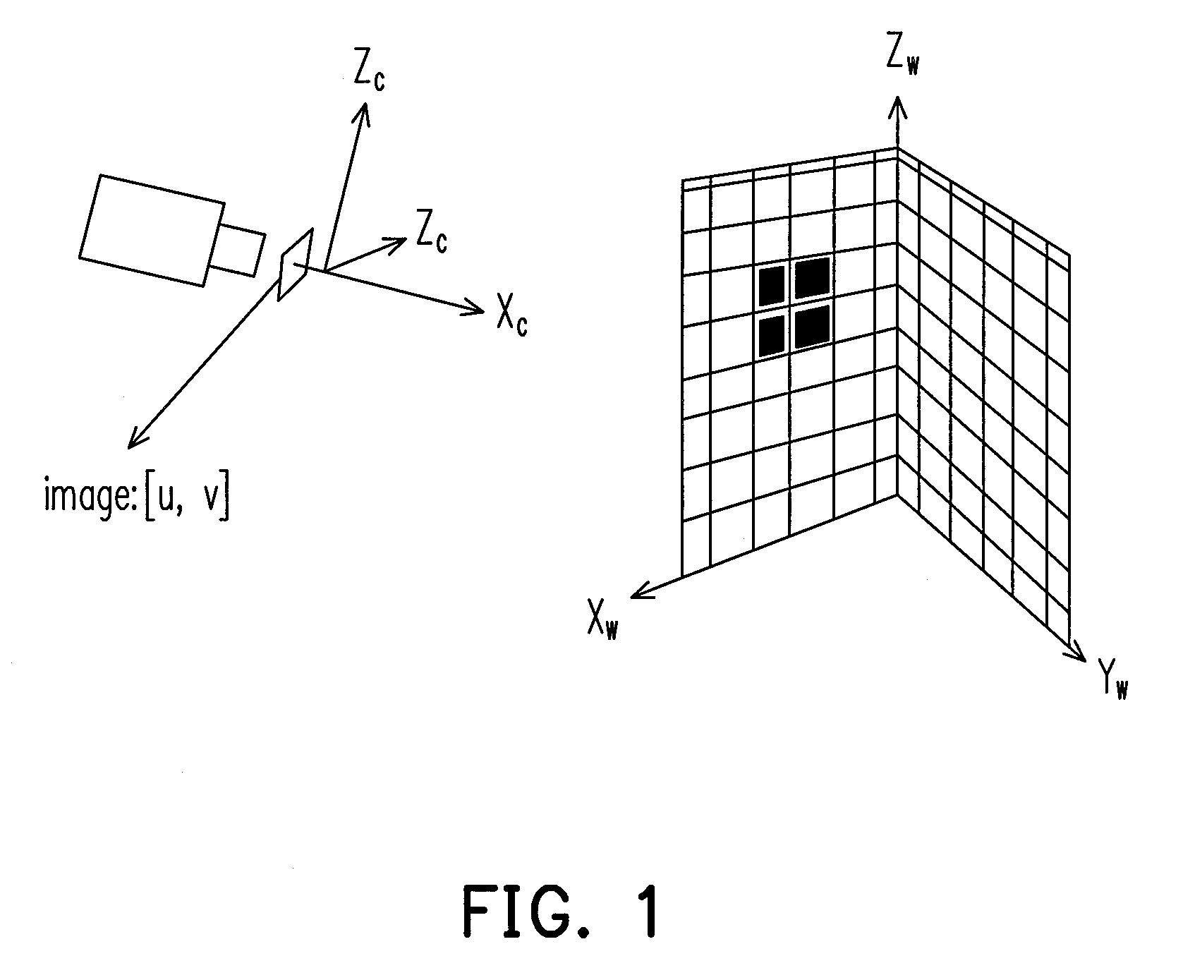
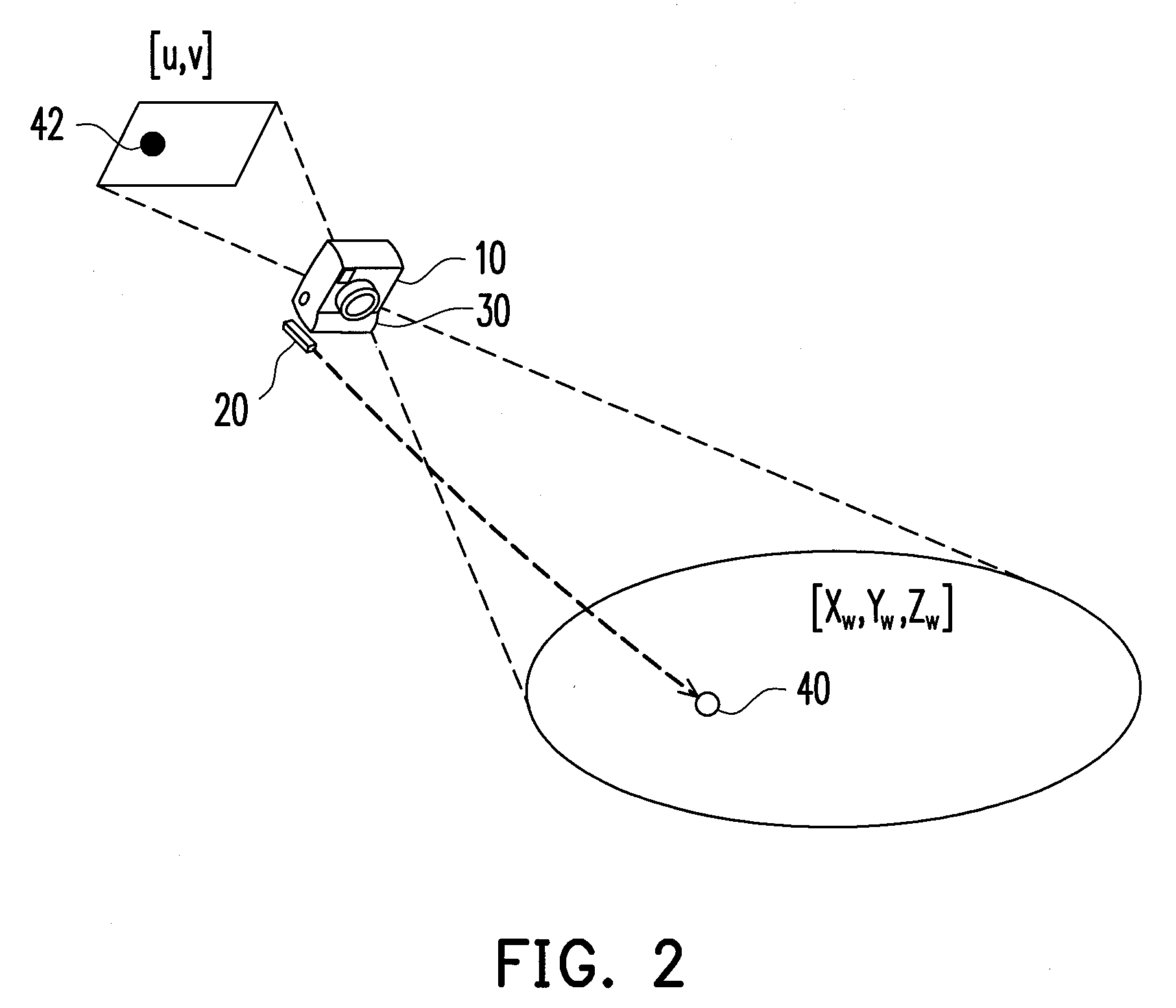
[0027]FIG. 2 is a schematic diagram illustrating an operation concept of a system according to an embodiment of the present invention. As shown in FIG. 2, a camera 10 is equipped with a point light source 20, and the point light source 20 is used for providing a light spot for the camera calibration. When a light beam emitted from the point light source 20 forms a light spot 40 in the environment, an image light spot 42 of the light spot 40 is then formed on an image plane of camera 10. The light spot 40 formed in the environment is defined by world coordinates [Xw, Yw, Zw], and the image light spot 42 is defined by image coordinates [...


PUM


Abstract

A camera with dynamic calibration and a method thereof is provided. The camera is first subject to an initial calibration. Then, a motion amount of the camera is calculated, and a plurality of motion amount estimation samples of the camera is generated according to the motion amount. Then, a weight of each of the motion amount estimation samples is calculated. Thereafter, the plurality of motion amount estimation samples is re-sampled based on the weights, and the camera is calibrated by the re-sampled estimated motion samples.

Description

CROSS-REFERENCE TO RELATED APPLICATION[0001]This application claims the priority benefit of Taiwan application serial no. 97151445, filed on Dec. 30, 2008. The entirety of the above-mentioned patent application is hereby incorporated by reference herein and made a part of specification.BACKGROUND OF THE INVENTION[0002]1. Field of the Invention[0003]The present invention relates to a calibration method of a camera.[0004]2. Description of Related Art[0005]For utilization of environmental security, a camera is generally used to monitor environmental status. Application of performing an accurate abnormity monitoring through an environmental image sensor has become a main development trend of such kind of product. Recently, with development of localization and navigation technology of service robots, integration of such kind of sensor is regarded as one of key techniques that influence an actual performance of the service robot.[0006]For a conventional camera, the calibration operation m...

Claims


Application Information

Patent Timeline
IPC IPC(8): H04N17/02
CPCG06T2207/10016G06T2207/30204G06T2207/30232G06T2207/30244H04N5/2224G06T7/73
Inventor HSIEH, HSIANG-WENYU, HUNG-HSIUWANG, WEI-HANWU, CHIN-CHIA
Owner IND TECH RES INST
Why Eureka
Try Eureka