Image stabilizer and optical instrument therewith

a technology which is applied in the field of image stabilizer and optical instrument therewith, can solve the problems of large storage space, large sag, and increase in size and cost of image stabilizer, and achieve the effect of reducing the size of image stabilizer and optical instrument, reducing the sag reaction force, and eliminating the harmful effect of sag

Active Publication Date: 2010-07-01
FUJIFILM CORP
View PDF13 Cites 113 Cited by
  • Summary
  • Abstract
  • Description
  • Claims
  • Application Information

AI Technical Summary

Benefits of technology

[0021]The present invention can eliminate the harmful effect of a sag of the flexible printed circuit, which a conventional image stabilizer has ever had. More specifically, the present invention obvi

Problems solved by technology

SAKAMOTO et al., MAEDA et al., STAVELY et al. and HIROTA et al. are applicable to an image stabilizer with a shiftable image sensor because the FPC is sagged, but still have problems caused by the sag of the FPC, that is, reaction force of the sag and variations in bending shape.
The long sag, however, requires a large storage space.
T

Method used


Image

  • Image stabilizer and optical instrument therewith
  • Image stabilizer and optical instrument therewith
  • Image stabilizer and optical instrument therewith

Examples


first embodiment

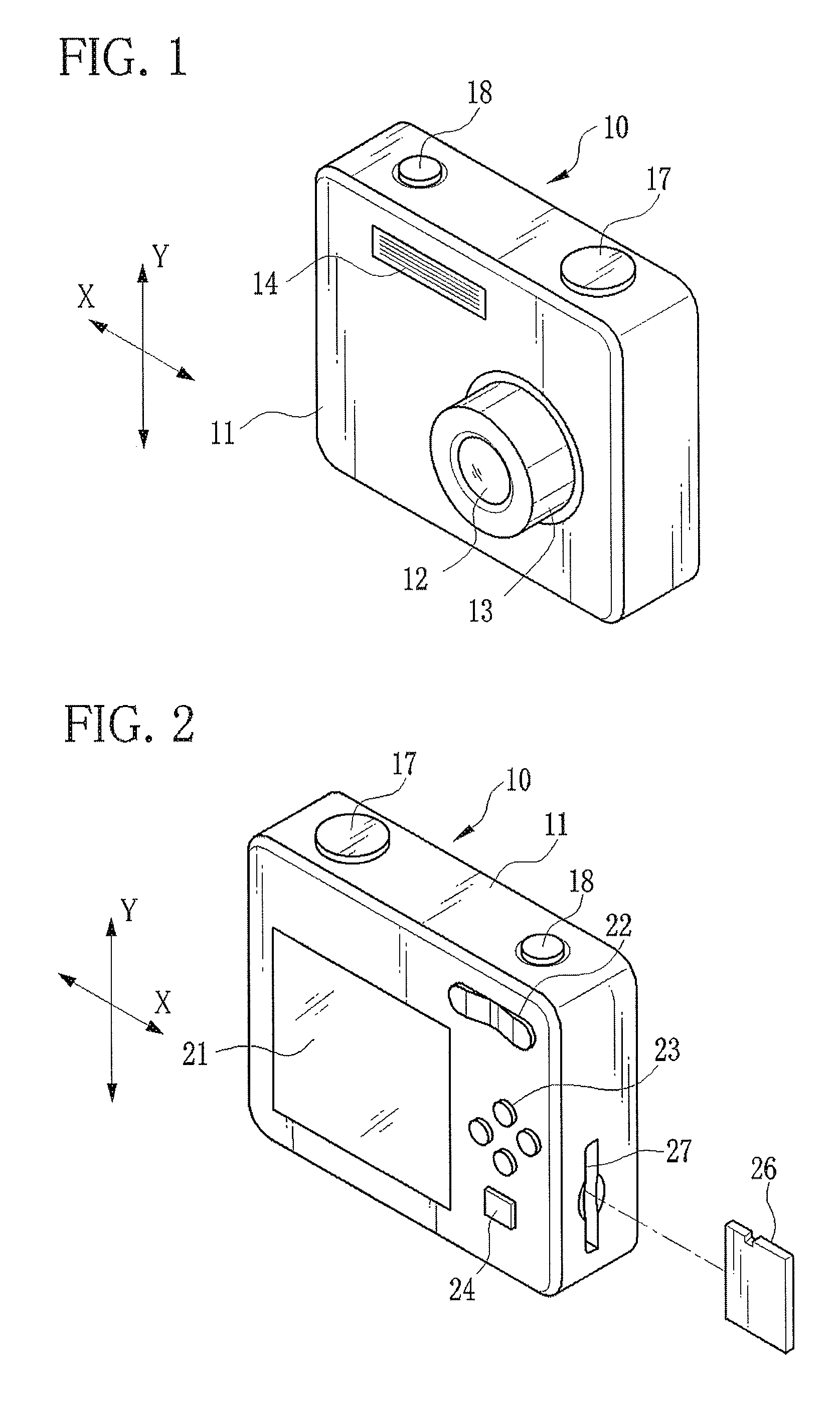
[0044]As shown in FIG. 1, a digital still camera 10 has a lens barrel 13 for containing an optical system 12, a flashlight emitter 14 for applying flashlight to an object and the like in a front face of a camera body 11.

[0045]On a top face of the camera body 11, there are provided an operation dial 17 and a shutter button 18. The operation dial 17 is used for turning the power on and off, and switching an operation mode (among a photographing mode, playback mode and the like). The shutter button 18 is a two-step push switch, and used for taking an image. Upon turning on a first-step switch SW1 by a half press of the shutter button 18, the digital still camera 10 makes preparation for image taking (exposure setting and focusing). After that, when a second-step switch SW2 is turned on by a full press of the shutter button 18, the digital still camera 10 captures a still image and stores image data on a memory card 26.

[0046]As shown in FIG. 2, a liquid crystal display (LCD) 21, a zoom ...

second embodiment

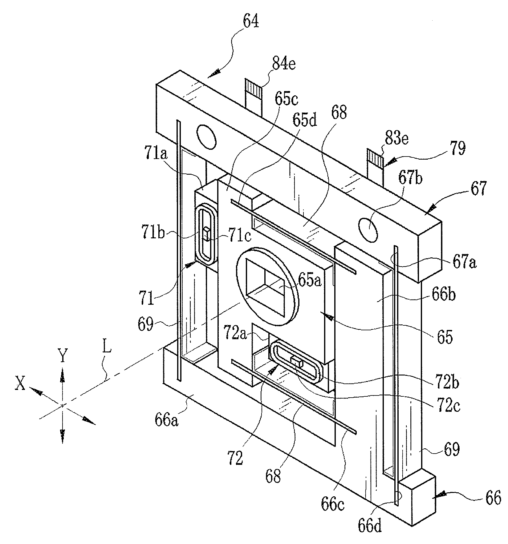
[0089]In the first embodiment, the FPC 79 is bifurcated into the first leading section 83 and the second leading section 84, and the first and second leading sections 83 and 84 are fitted on all of the pair of horizontal leaf springs 68 and the pair of vertical leaf springs 69. In a second embodiment, an FPC is fitted on one of the horizontal leaf springs 68 and one of the vertical leaf springs 69. The same reference numbers as the first embodiment indicate substantially the same elements or parts, and description thereof will be omitted.

[0090]An FPC 91 of a CCD support mechanism 90, as shown in FIG. 9, has a leading section 92 that extends downwardly from the CCD connection section 80. The leading section 92 has an inner frame fitting part 92a, a horizontal leaf spring fitting part 92b, an outer frame fitting part 92c, a vertical leaf spring fitting part 92d and a terminal part 92e, and individual parts are divided by fold lines. The fitting parts 92a to 92d are fitted on the rear ...

third embodiment

[0093]The FPC 79 of the first embodiment may be reinforced to act as the pair of horizontal leaf springs 68 and the pair of vertical leaf springs 69. A third embodiment in which an FPC is used as the leaf springs will be hereinafter described. The same reference numbers as the first and first embodiments indicate substantially the same elements or parts, and description thereof will be omitted.

[0094]In a CCD support mechanism 100 shown in FIG. 10, the inner frame 65, the outer frame 66 and the base block 67 are identical to those of the first embodiment. An FPC 101 has almost the same shape as the FPC 79 of the first embodiment. The FPC 101 is provided with a pair of horizontal leaf spring sections 102 corresponding to the horizontal leaf spring fitting parts 83b and 84b of the FPC 79, and a pair of vertical leaf spring sections 103 corresponding to the vertical leaf spring fitting parts 83d and 84d. Both ends of each horizontal leaf spring section 102 are fitted into the slits 65d ...


PUM


Abstract

An image stabilizer has a base block, an inner frame for holding a CCD, an outer frame, a pair of horizontal leaf springs, a pair of vertical leaf springs, voice coil motors (VCMs) and a flexible printed circuit (FPC). Upon a shake of a digital still camera due to hand-held shooting, the VCMs shift the inner or outer frame while bending the horizontal or vertical leaf springs so that the CCD is shifted to counteract the camera shake. The FPC connected to the CCD and the VCMs is routed from the inner frame, through the horizontal leaf spring, the outer frame and the vertical leaf spring, and pulled out above the base block. The FPC is glued to the horizontal and vertical leaf springs, and elastically bent together with the horizontal and vertical leaf springs.

Description

BACKGROUND OF THE INVENTION[0001]1. Field of the Invention[0002]The present invention relates to an image stabilizer for correcting an image blur due to hand-held shooting, and an optical instrument therewith.[0003]2. Description Related to the Prior Art[0004]Many optical instruments including digital still cameras have an image stabilizer or a shake correction device for correcting an image blur caused by vibration or a camera shake due to hand-held shooting. The image stabilizer is constituted of a shake detector for detecting the camera shake, a holder for movably holding an optical element such as a taking lens or an image sensor, a computing unit, an actuator for shifting the holder in a plane where the optical element is orthogonal to a photography optical axis, and a position detector for detecting the position of the optical element. The computing unit calculates which direction and how much the optical element should be shifted, based on a detection result of the shake dete...

Claims


Application Information

Patent Timeline
IPC IPC(8): H04N5/228G02B27/64
CPCG02B27/646G03B5/00H04N5/23248H04N5/23258H04N5/23287G03B2205/0069G03B2205/0038H04N23/68H04N23/6812H04N23/687
Inventor MAKIMOTO, AKIHIROHAYASHI, JUNJITOKIWA, KENTARO
Owner FUJIFILM CORP
Why Eureka
Try Eureka