Switching mechanism for optical component, lens barrel, and imaging device

Inactive Publication Date: 2010-07-01
SONY CORP
View PDF4 Cites 9 Cited by
  • Summary
  • Abstract
  • Description
  • Claims
  • Application Information

AI Technical Summary

Benefits of technology

[0014]According to the embodiments of the present invention, the rotation feed direction in which the optical component is driven toward the restriction member at the optical axis position with a rotation of the worm provided to the drive motor is aligned with a direction in which the optical component comes close to the drive motor. Hence, by further driving the drive motor in a state where the optical component is restricted by the restriction member, a force is exerted in a direction in which the rotation shaft attached with the worm is pulled out from the drive motor. However, a force pulling back the rotation shaft into the drive motor acts on the rotation shaft and a force acts in a

Problems solved by technology

In the case of the manual switching, there is a risk of failure because an extra load may possibly be applied on the mechanical mechanism depending on a manner of operation by the user.
Meanwhile, in the case of the electrical switching, a link mechanism used to transmit drive power from the motor becomes co

Method used


Image

  • Switching mechanism for optical component, lens barrel, and imaging device
  • Switching mechanism for optical component, lens barrel, and imaging device
  • Switching mechanism for optical component, lens barrel, and imaging device

Examples


first embodiment

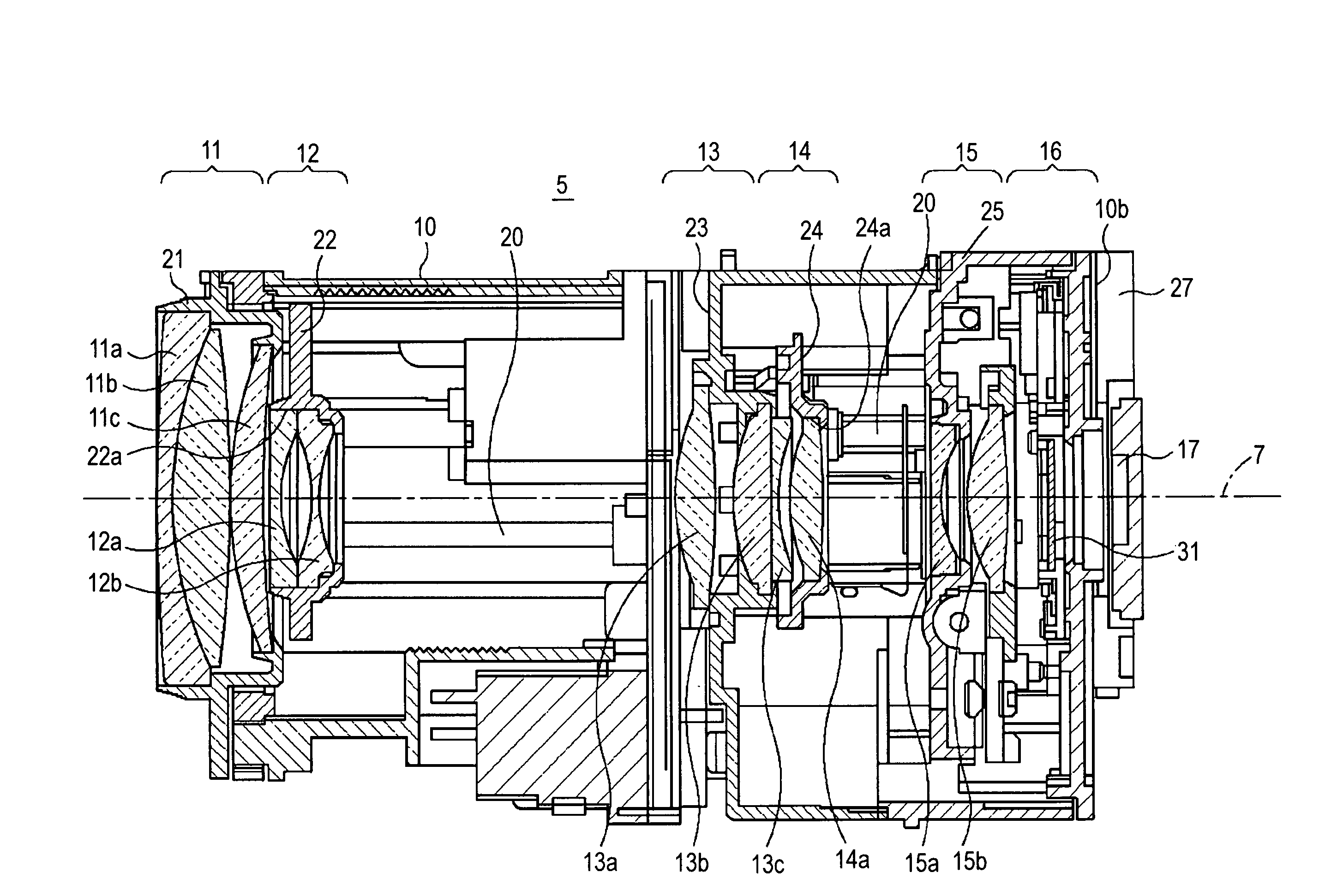
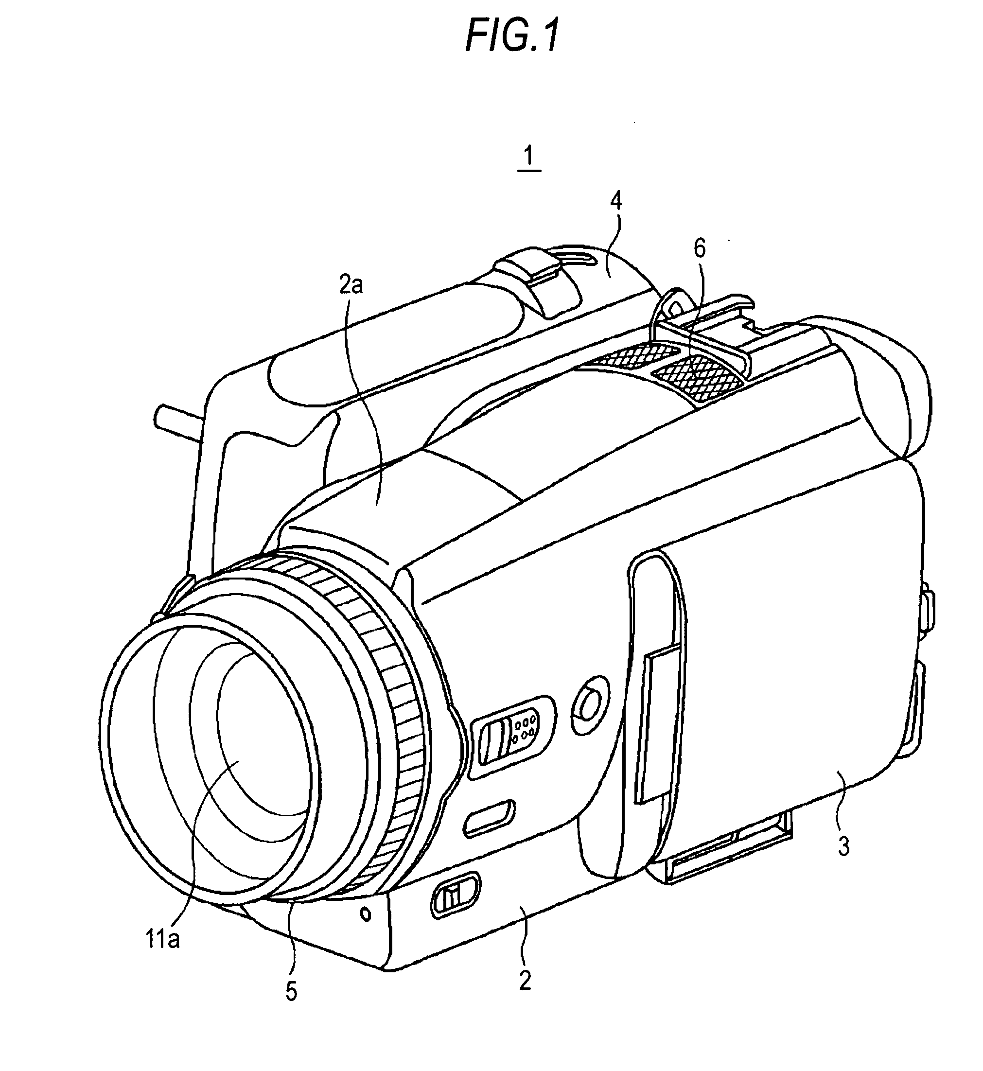
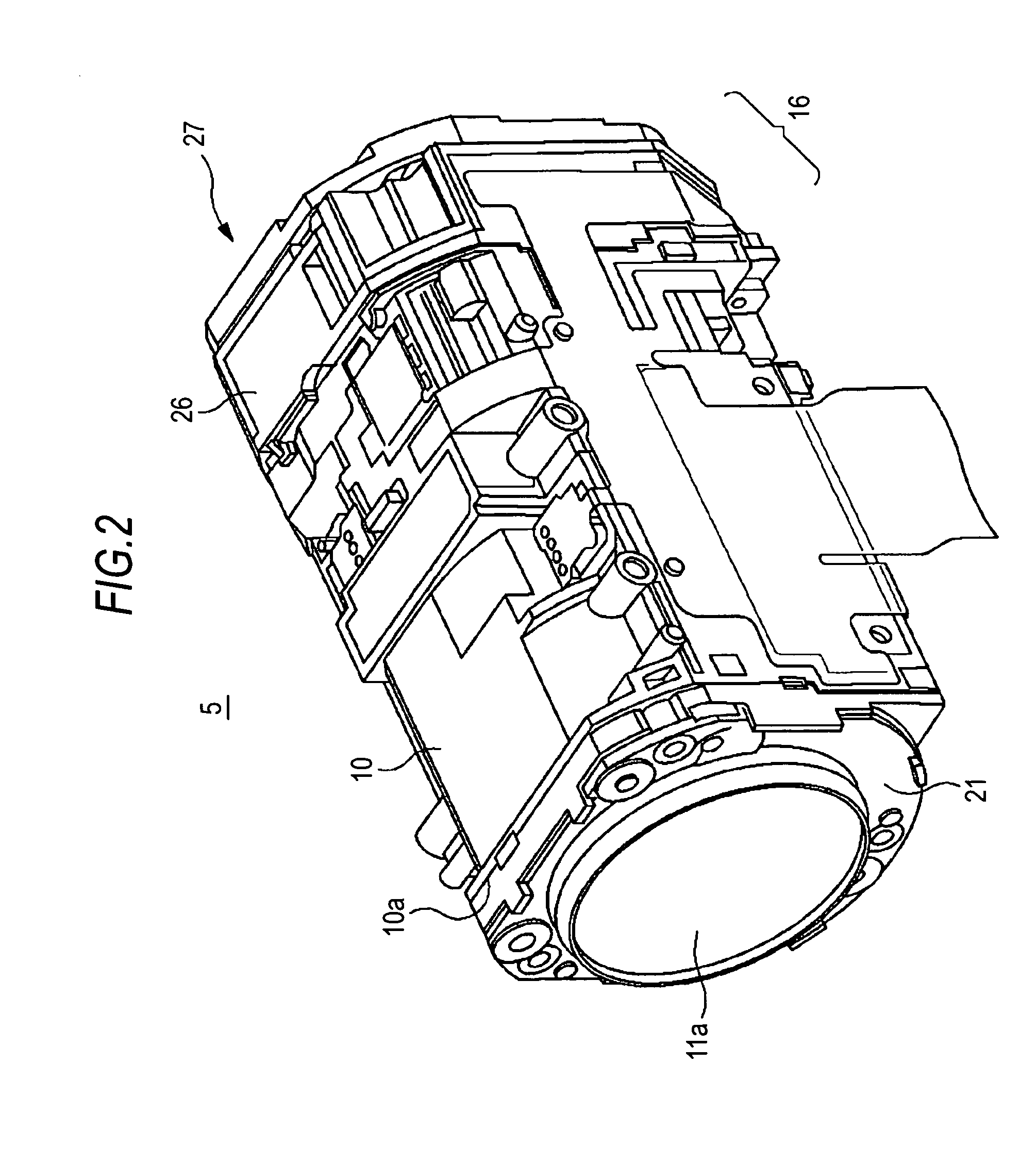
[0036]A lens barrel 5 according to an embodiment of the present invention described hereinafter as a first embodiment is employed in a digital video camera 1 as shown in FIG. 1 and it is furnished with a so-called zoom function of making a focal point variable. It should be appreciated, however, that the lens barrel 5 is not necessarily employed in the digital video camera 1 and it may be integrally attached to an electronic still camera chiefly taking still images or employed as an interchangeable lens of a single-lens reflex camera.

Imaging Device

[0037]The digital video camera 1 described herein as an imaging device includes, for example, a main body portion 2, a panel portion 3 attached to the main body portion 2 on one side surface in an openable and closable manner, and a grip portion 4 attached to the main body portion 2 on the other side surface opposite to the panel portion 3 in a rotatable manner.

[0038]The main body portion 2 has an imaging unit that takes an image of a subj...

second embodiment

[0075]An infrared light cut glass switching portion according to another embodiment of the present invention will now be described as a second embodiment. Hereinafter, the configurations same as those of the infrared light cut glass switching portion 16 are labeled with the same reference numerals and descriptions are omitted.

[0076]The infrared light cut glass switching portion described in the second embodiment is provided with a drive mechanism 50 having a worm 51 and a worm wheel 52 as shown in FIG. 10A through FIG. 11C instead of the worm 44 and the worm wheel 32c of the drive mechanism 40.

[0077]As is shown in FIG. 10A, the worm 51 of the drive mechanism 50 is provided with a gear wheel having the same rotation feed direction as the worm 44 and it is attached to the rotation shaft 43 of the drive motor 41. An abutment portion 53 is provided to the tip end of the gear wheel. Rotations from the drive motor 41 are restricted as the abutment portion 53 of the worm 51 abuts on a rest...


PUM


Abstract

A switching mechanism for optical component includes: an optical component; a holder member holding the optical component; a drive mechanism having a drive motor that drives the optical component held by the holder member to rotate on a plane orthogonal to an optical axis from an optical axis position at which the optical component is on the optical axis to an evacuation position at which the optical component is off the optical axis; and a restriction member restricting a rotation of the holder member, by which at least a rotation of the optical component held by the holder member is restricted at the optical axis position. The drive mechanism includes the drive motor, a worm attached to a rotation shaft of the drive motor, and a worm wheel meshed with the worm and provided to the holder member.

Description

CROSS-REFERENCE TO RELATED APPLICATION[0001]The present application claims priority from Japanese Patent Application No. JP 2008-334609 filed in the Japanese Patent Office on Dec. 26, 2008, the entire content of which is incorporated herein by reference.BACKGROUND OF THE INVENTION[0002]1. Field of the Invention[0003]The present invention relates to a switching mechanism for optical component employed in a camera or the like to allow switching between a state where an optical component that shields infrared light is on the optical axis and a state where the optical component is off the optical axis, a lens barrel using this switching mechanism, and an imaging device provided with this lens barrel.[0004]2. Description of Related Art[0005]In a video camera and a digital still camera configured to take a moving image and a still image, a lens barrel is provided to a camera main body as an integral part or as a separate component. The lens barrel includes, for example, a lens group furni...

Claims


Application Information

Patent Timeline
IPC IPC(8): H04N5/225
CPCH04N5/2251H04N5/2254H04N23/55H04N23/50
Inventor ISHII, ATSUYANISHIDA, TADATSUGUHORIDAN, ATSUSHIMAENISHI, JUNICHI
Owner SONY CORP
Why Eureka
Try Eureka