Connecting device and electronic device having same

Inactive Publication Date: 2010-07-01
HONG FU JIN PRECISION IND (SHENZHEN) CO LTD +1
View PDF6 Cites 11 Cited by
  • Summary
  • Abstract
  • Description
  • Claims
  • Application Information

AI Technical Summary

Benefits of technology

[0005]Therefore, it is desirable to provide a connecting device and an electronic device having the same which can overcome the described limitations.

Problems solved by technology

One of the challenges of utilizing such an electronic device is that the random location of the connection ports decrease dustproof effectiveness of the housing.

Method used


Image

  • Connecting device and electronic device having same
  • Connecting device and electronic device having same
  • Connecting device and electronic device having same

Examples


Embodiment Construction

[0013]Embodiments of the disclosure will now be described in detail with reference to the drawings.

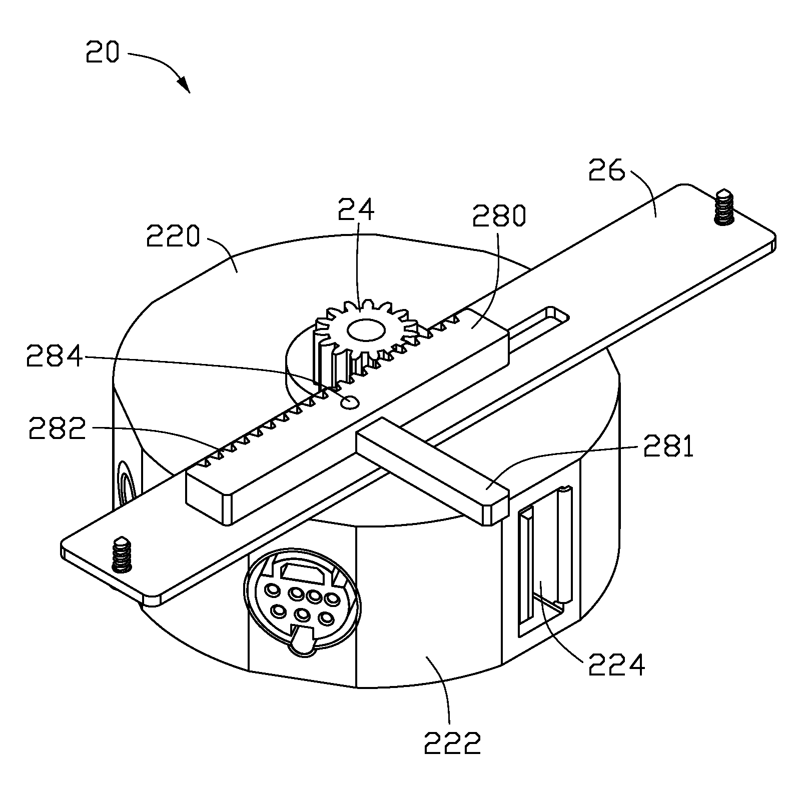
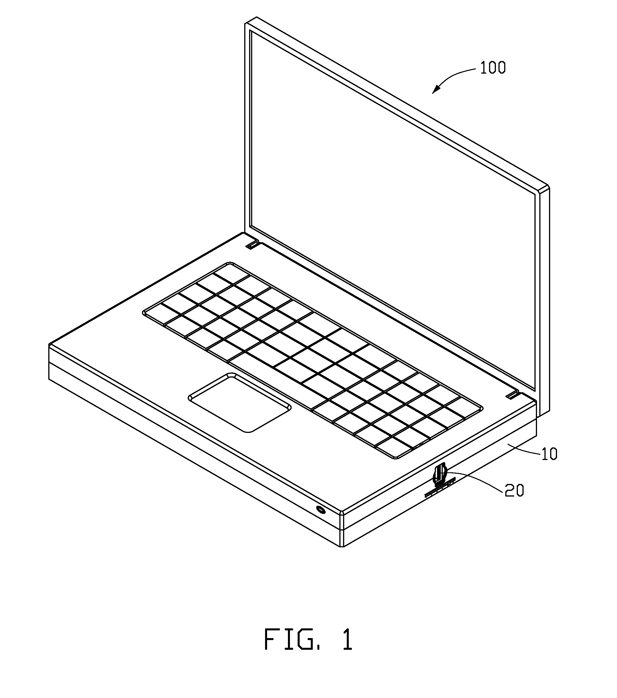
[0014]FIG. 1 shows an electronic device 100 in accordance with an exemplary embodiment. The electronic device 100 includes a housing 10 and a connecting device 20 received in the housing 10. In this embodiment, the electronic device 100 is a laptop computer.

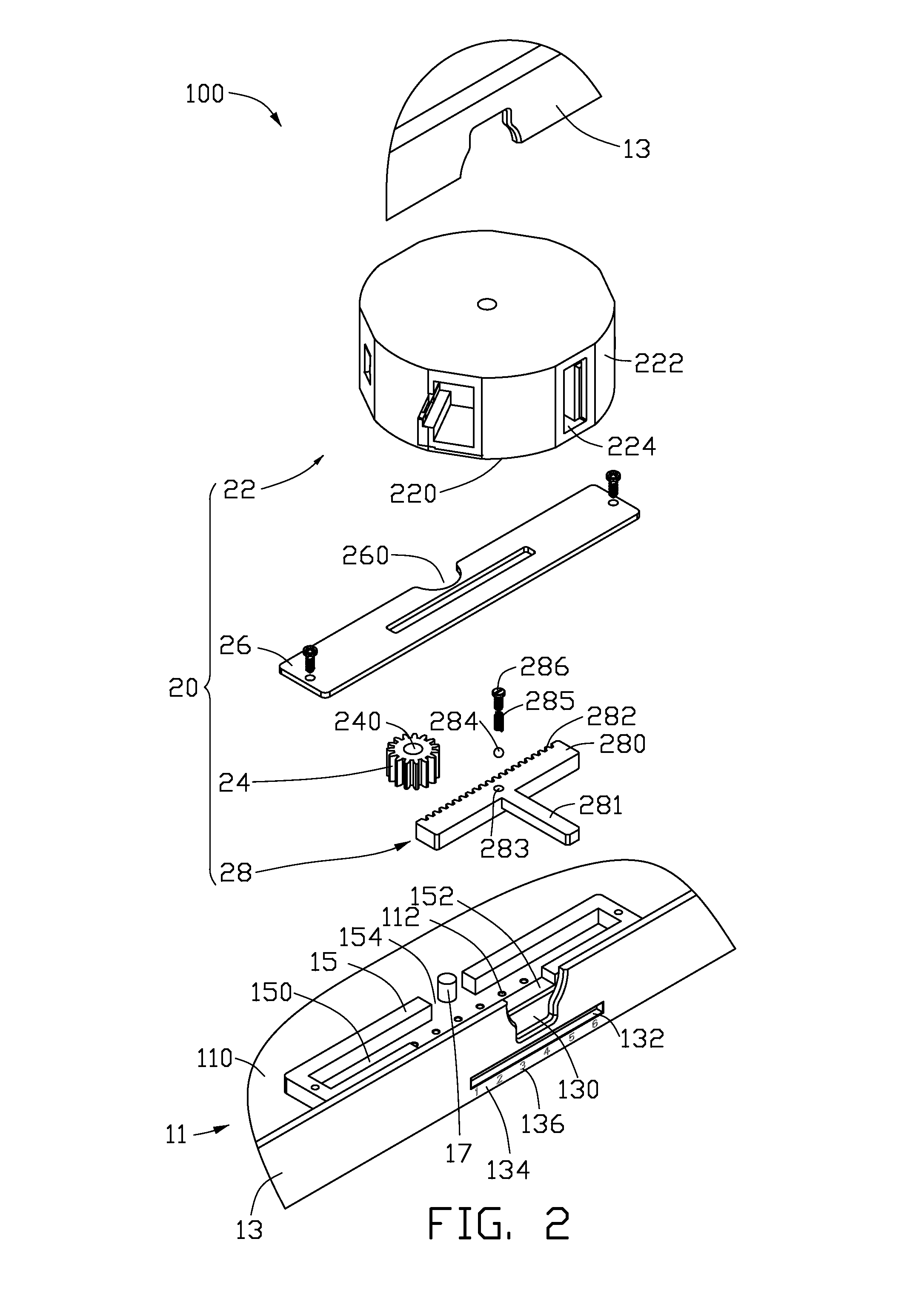
[0015]Referring to FIG. 2, the housing 10 includes a bottom plate 11 including an inner surface 110, a sidewall 13 substantially extending perpendicularly from the inner surface 110, and a rectangular frame 15 fixed on the inner surface 110 adjacent the sidewall 13.

[0016]The bottom plate 11 defines six positioning blind holes 112 arranged in a straight line substantially parallel to the sidewall 13. Each positioning blind hole 112 defines a spherical inner surface (not labeled).

[0017]The sidewall 13 defines an opening 130 and an elongated slot 132 beneath the opening 130, and includes a ruler-shaped indicating sheet 134 pasted immed...


PUM


Abstract

A connecting device is used in an electronic device. The electronic device includes a housing including a bottom plate, a sidewall and a pivot shaft. The sidewall extends perpendicularly from the bottom plate and defines an opening and a slot. The pivot shaft extends perpendicularly from the bottom plate and is aligned with the slot. The connecting device includes a driven gear, a main body and a driving member. The driven gear is disposed on the bottom plate, rotatably positioned by the pivot shaft, and fixed to the main body. The main body defines more than one connection port. The driving member is engaged with the driven gear and protrudes out from the slot. The driving member is operable to rotate the driven gear and the main body around the pivot shaft, thereby switches the connection ports to be exposed to the outside of the housing via the opening.

Description

BACKGROUND[0001]1. Technical Field[0002]The present disclosure relates to connecting devices and, particularly, to a connecting device having more than one connection port and an electronic device having the same.[0003]2. Description of Related Art[0004]Electronic devices typically include a housing and define a number of connection ports, such as audio ports, video ports and universal serial bus (USB) ports, which are randomly located around the housing of the electronic devices. One of the challenges of utilizing such an electronic device is that the random location of the connection ports decrease dustproof effectiveness of the housing.[0005]Therefore, it is desirable to provide a connecting device and an electronic device having the same which can overcome the described limitations.BRIEF DESCRIPTION OF THE DRAWINGS[0006]FIG. 1 is an isometric, schematic view of an electronic device according to an exemplary embodiment.[0007]FIG. 2 is an isometric, exploded, partially sectional, ...

Claims


Application Information

Patent Timeline
IPC IPC(8): H05K5/00F16H19/02F16H19/04
CPCG06F1/1616G06F1/1656H01R27/00H01R2201/06Y10T74/18808Y10T74/188
Inventor LAI, JIN-SHI
Owner HONG FU JIN PRECISION IND (SHENZHEN) CO LTD
Why Eureka
Try Eureka