
Engine speed calculation device and engine sound generation device

Inactive Publication Date: 2010-07-01
YAMAHA CORP
View PDF10 Cites 48 Cited by
  • Summary
  • Abstract
  • Description
  • Claims
  • Application Information

AI Technical Summary

Benefits of technology

[0006]It is an object of the present invention to provide an engine speed calculation device and an engine sound generation device, which are capable of generating an artificial engine sound close to the actual engine sound produced by an engine-driven vehicle even when the calculated engine speed does not vary in proportion to the traveling speed of a vehicle such as an electric vehicle and a hybrid vehicle.
[0008]In the above, the engine speed calculation unit calculates the virtual engine speed without using the vehicle speed and with reference to the vehicle-nondependent engine speed memory on the condition that the virtual engine speed is not proportional to the vehicle speed. This prevents the virtual engine speed calculation unit from miscalculating the virtual engine speed based on the vehicle speed which is not proportional to the virtual engine speed, thus prevent the artificially affected engine sound from being produced based on the miscalculated virtual engine speed. In other words, the engine sound generation device of the present invention is capable of generating the common engine speed matching the behavior of an engine in an electric vehicle driven by an electric motor.
[0010]Alternatively, the vehicle-nondependent engine speed memory stores a table of an engine speed increase rate in connection to the accelerator opening, thus allowing the engine speed calculation unit to read the engine speed increase rate from the table in correspondence with the accelerator opening and to thereby calculate the virtual engine speed by use of an elapsed time. The virtual engine speed is varied continuously with respect to time while following up with variations of the accelerator opening. In other words, it is possible to prevent the virtual engine speed from being varied discontinuously, thus precisely calculating the virtual engine speed nondependent upon the vehicle speed.

Problems solved by technology

This adversely causes a traffic problem in that pedestrians may hardly notice electric vehicles approaching them.
Since engine-driven vehicles differ from electric vehicles in sounds generated during driving at the same velocity, drivers who are accustomed to engine-driven vehicles but are not accustomed to electric vehicles may have a sense of incongruity in driving electric vehicles.

Method used


Image

  • Engine speed calculation device and engine sound generation device
  • Engine speed calculation device and engine sound generation device
  • Engine speed calculation device and engine sound generation device

Examples


first embodiment

1. First Embodiment

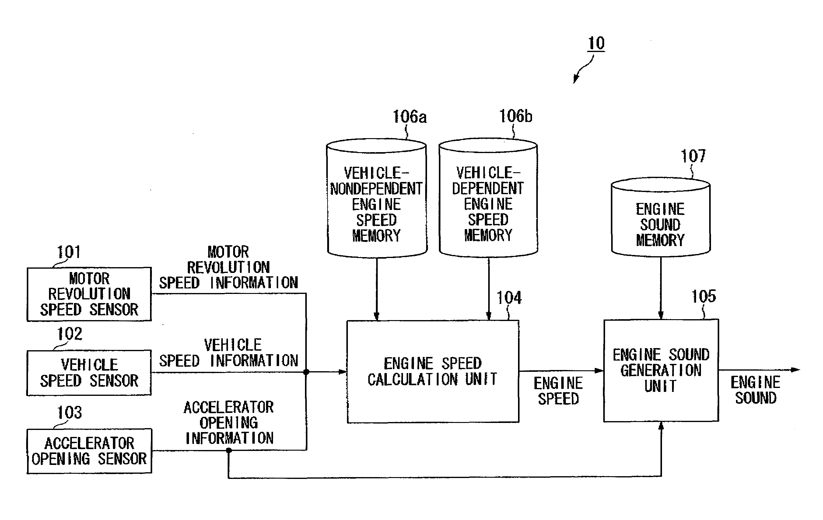
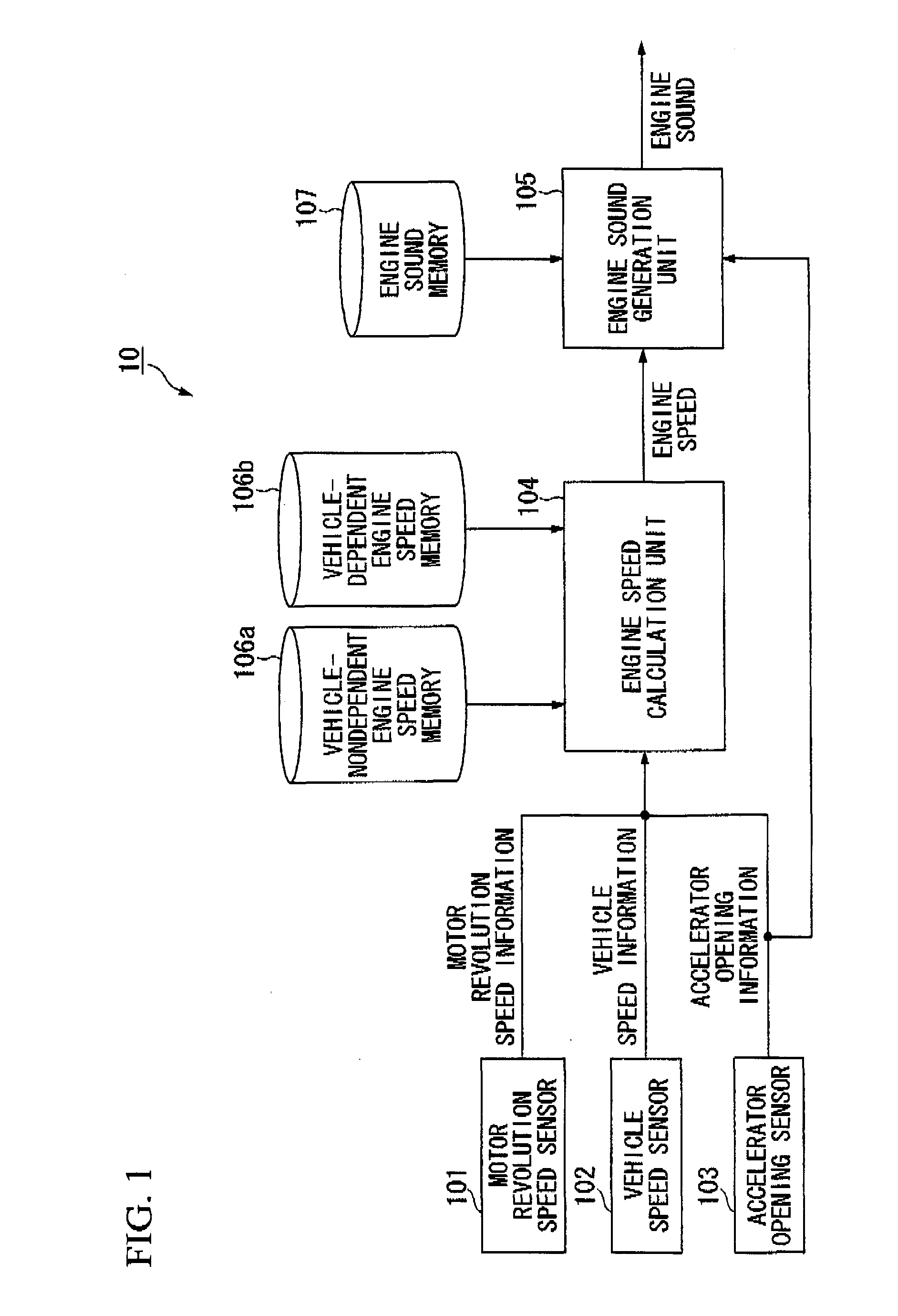
[0022]FIG. 1 is a block diagram showing the constitution of an engine sound generation device 10 according to a first embodiment of the present invention.

[0023]The engine sound generation device 10 is constituted of a motor revolution speed sensor 101, a vehicle speed sensor 102, an accelerator opening sensor 103, an engine speed calculation unit 104, an engine sound generation unit 105, a vehicle-nondependent engine speed memory 106a, a vehicle-dependent engine speed memory 106b, and an engine sound memory 107. The following description is related to an electric vehicle equipped with an electric motor only, in which the terms such as engine and transmission are used as imaginary factors.

[0024]The motor revolution speed sensor 101 detects the revolution speed of an electric motor (serving as a driving source of a four-wheeled vehicle) so as to produce motor revolution speed information. The vehicle speed sensor 102 detects the revolution speed of wheels of the veh...

second embodiment

2. Second Embodiment

[0042]Next, a second embodiment of the present invention will be described by way of the engine sound generation device 10 shown in FIG. 1, wherein the constitution and operation of the second embodiment are identical to those of the first embodiment except for the following point.

[0043]It is possible to presume that the virtual engine speed does not vary in proportion to the vehicle speed (in the semi-engagement of the clutch, for instance) while the vehicle speed is increased from 0 km / h to reach 10 km / h.

[0044]Considering the above situation in starting up the engine of the vehicle, the second embodiment introduces a table identifying the correspondence between the accelerator opening and the virtual engine speed (which varies with respect to time), with which the engine speed calculation unit 104 calculates the virtual engine speed.

[0045]FIGS. 6A and 6B shows the tables of time-related variations of the virtual engine speed, which is stored in the vehicle-nond...

third embodiment

3. Third Embodiment

[0048]Next, a third embodiment of the present invention will be described by way of the engine sound generation device 10 shown in FIG. 1, wherein the constitution of the third embodiment is identical to that of the first embodiment except for the following point.

[0049]The third embodiment is characterized in that the engine speed calculation unit 104 refers to the predetermined relationship between the accelerator opening and the virtual engine speed increase rate on the condition that the virtual engine speed does not vary in proportion to the vehicle speed.

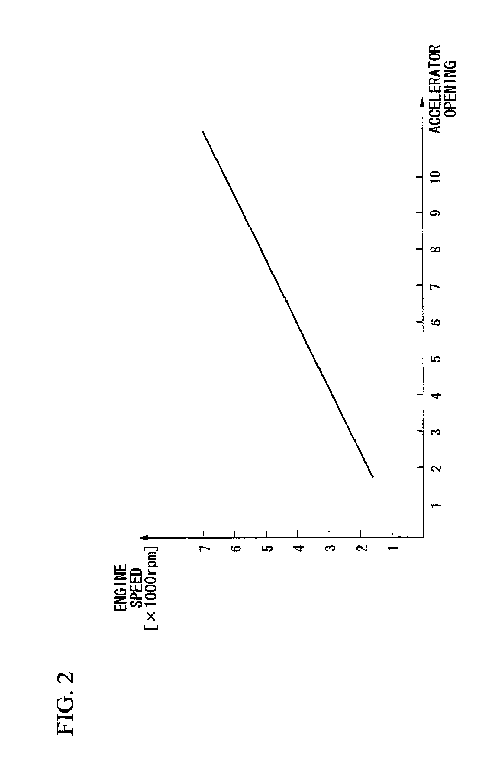
[0050]FIG. 7 is a graph showing the content of a table stored in the vehicle-nondependent engine speed memory 106a, wherein the horizontal axis represents the accelerator opening (e.g. ranges 1-10), and the vertical axis represents the engine speed increase rate in units of 1,000 rpm / s, thus showing linear variations of the engine speed increase rate in connection to the accelerator opening. According to FIG....


PUM


Abstract

An engine sound generation device adapted to an electric vehicle includes an engine speed calculation unit which calculates the virtual engine speed based on the motor revolution speed, vehicle speed, and acceleration opening. The engine speed calculation unit calculates the virtual engine speed with reference to the vehicle-dependent engine speed memory on the condition that the virtual engine speed is deemed proportional to the vehicle speed. In addition, the engine speed calculation unit calculates the virtual engine speed with reference to the vehicle-nondependent engine speed memory on the condition that the virtual engine speed is not deemed proportional to the vehicle speed, thus generating the common engine sound matching the behavior of an engine in a prescribed event such as the startup of the electric vehicle and the semi-engagement of a clutch.

Description

BACKGROUND OF THE INVENTIONField of the Invention[0001]The present invention relates to engine speed calculation devices and engine sound generation devices for generating engine sound simulated in traveling conditions of four-wheeled vehicles and motorcycles.[0002]The present application claims priority on Japanese Patent Application No. 2008-334233, the content of which is incorporated herein by reference.DESCRIPTION OF THE RELATED ART[0003]Recently, electric vehicles driven by electric motors and hybrid vehicles driven by engines and electric motors have widely spread among people highly concerned with environmental conservation. Compared to conventional four-wheeled vehicles, electric vehicles and hybrid vehicles are advantageous in that they generate very small noise while traveling. This adversely causes a traffic problem in that pedestrians may hardly notice electric vehicles approaching them. Since engine-driven vehicles differ from electric vehicles in sounds generated duri...

Claims


Application Information

Patent Timeline
IPC IPC(8): H04B1/00G06F15/00
CPCB60L3/00B60Q5/008G10K15/02
Inventor ISOZAKI, YOSHIMASA
Owner YAMAHA CORP
Learn More