
Receiving part for receiving a rod for coupling the rod to a bone anchoring element and bone anchoring device with such a receiving part

Active Publication Date: 2010-07-01
BIEDERMANN TECH GMBH & CO KG
View PDF25 Cites 82 Cited by
  • Summary
  • Abstract
  • Description
  • Claims
  • Application Information

AI Technical Summary

Benefits of technology

[0010]It is the object of the invention to provide an improved receiving part for receiving a rod for coupling the rod to a bone anchoring element and a bone anchoring device with such a receiving part, which has small size while simultaneously providing a safe final locking and / or which can be used as a modular system.
[0011]The bone anchoring device according to an embodiment of the invention comprises few elements, which reduces the costs of manufacturing and which facilitates handling. It makes use of the principle of clamping the head of the bone anchoring element circumferentially from the lateral sides, which reduces the force necessary to safely clamp the head. The design of the bone anchoring device allows to further reduce the dimension in terms of height as well as in terms of the bottom outer diameter, which is particularly suitable for applications, where small-sized anchoring devices are utilized, such as in the field of cervical spinal surgery or pediatric applications, trauma and minimally invasive applications.
[0013]Since the height of the locking ring is smaller than the height of the head receiving portion, the receiving part has a profile with a small diameter. The pressure exerted via the locking ring onto the head receiving portion is largest at a position of the largest diameter of the head of the bone anchoring element. Therefore, the locking ring does not have to extend up to the open end of the head receiving portion, which allows for a locking ring with a reduced diameter at the bottom side.
[0014]A locking ring is movable between a position in which the head is not clamped and a position in which the head is locked. The locking ring can be releasably held in either of the two end positions, which makes handling very convenient. The locking ring may be held also in a preliminary locking position, which allows secondary adjustments of the rod while maintaining the angular position of the receiving part with respect to the bone anchoring element.

Problems solved by technology

Furthermore, the size of the known bone anchoring device is quite large, as the locking collar and the top locking nut extend substantially outward from the diameter of the coupling element.

Method used


Image

  • Receiving part for receiving a rod for coupling the rod to a bone anchoring element and bone anchoring device with such a receiving part
  • Receiving part for receiving a rod for coupling the rod to a bone anchoring element and bone anchoring device with such a receiving part
  • Receiving part for receiving a rod for coupling the rod to a bone anchoring element and bone anchoring device with such a receiving part

Examples


Embodiment Construction

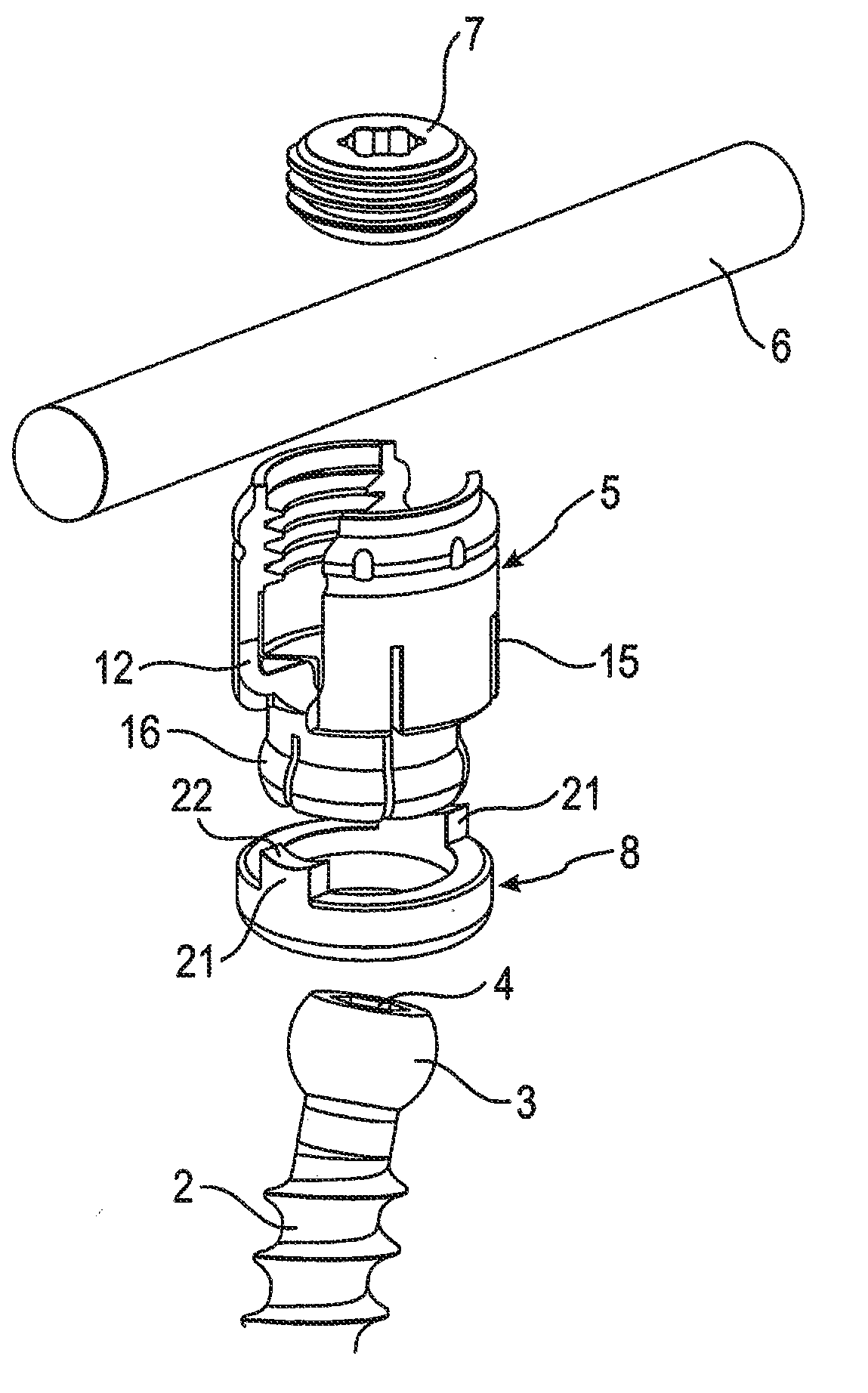
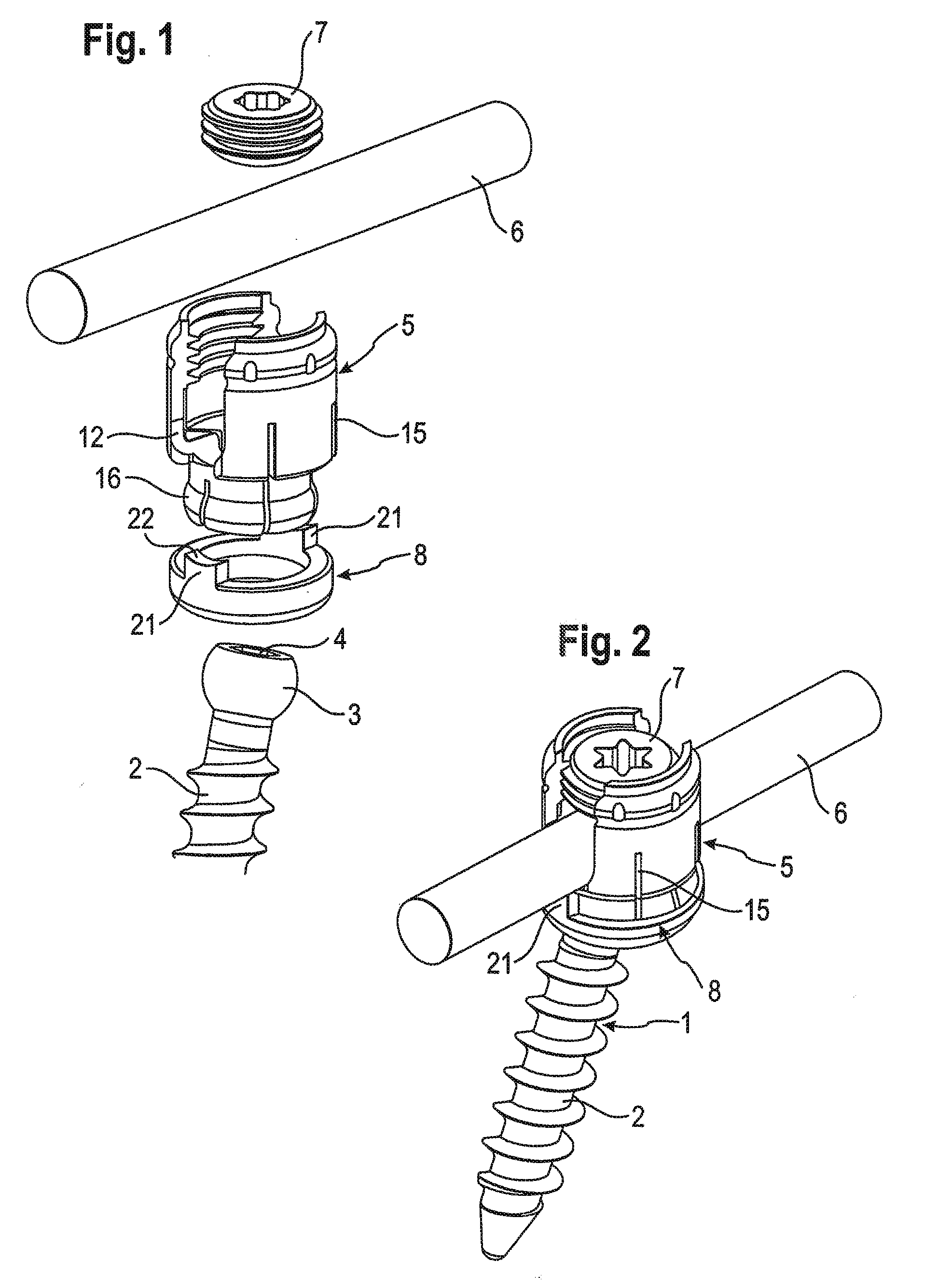
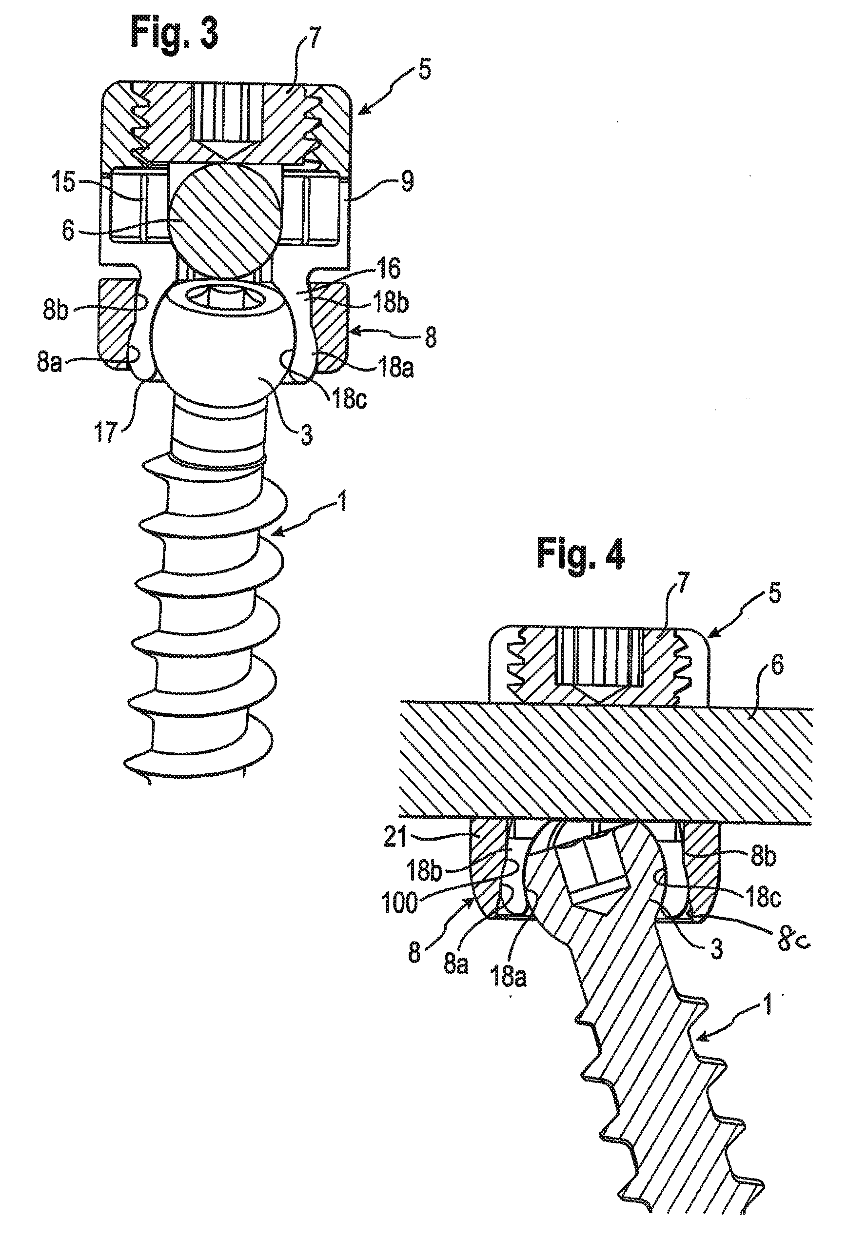
[0038]As shown in FIGS. 1 to 4, the bone anchoring device according to embodiments of the present invention comprise a bone anchoring element 1 in the form of a bone screw having a threaded shaft 2 and a head 3 with a curved surface portion, in these embodiments a spherical segment-shaped head. The head 3 has a recess 4 for engagement with a screwing-in tool. The bone anchoring device further comprises a receiving part body 5 for receiving a rod 6 to connect it to the bone anchoring element 1. Further, a closure element 7 in the form of an inner screw is provided for securing the rod 6 in the receiving part body 5. In addition, the bone anchoring device comprises a locking ring 8 for locking the head in the receiving part body 5.

[0039]As can be seen in particular in FIGS. 5 to 9, the receiving part body 5 comprises a rod receiving portion 9, which is substantially cylindrical and which has a first end 9a, and an opposite second end 9b. The rod receiving portion 9 has a coaxial first...


PUM


Abstract

A receiving part for receiving a rod for coupling the rod to a bone anchoring element includes a receiving part body including: a rod receiving portion with a channel for receiving a rod, and a head receiving portion for accommodating a head of a bone anchoring element, the head receiving portion having an open end and being flexible for inserting and clamping of the head, and an exterior surface with a curved portion; and a locking ring around the head receiving portion, wherein the locking ring has an interior surface with a curved portion for engagement with the curved portion of the exterior surface of the head receiving portion for locking a position of the head relative to the head receiving portion.

Description

CROSS-REFERENCE TO RELATED APPLICATIONS)[0001]The present application claims the benefit of U.S. Provisional Patent Application Ser. No. 61 / 141,191, filed Dec. 29, 2008, the contents of which are hereby incorporated by reference in their entirety, and claims priority from European Patent Application EP 08 022 510.5, filed Dec. 29, 2008, the contents of which are hereby incorporated by reference in their entirety.BACKGROUND[0002]1. Field of the Invention[0003]The invention relates to a receiving part for receiving a rod for coupling the rod to a bone anchoring element and a bone anchoring device with such a receiving part. The head of the bone anchoring element is locked in the receiving part by compression of a head receiving portion of the receiving part laterally surrounding the head by means of a locking ring. The head receiving portion of the receiving part has an exterior surface with a curved portion and the locking ring has an interior surface with a curved portion, which pre...

Claims


Application Information

Patent Timeline
IPC IPC(8): A61B17/86
CPCA61B17/7032A61B17/7037
Inventor BIEDERMANN, LUTZMATTHIS, WILFRIEDDANNECKER, BERTHOLD
Owner BIEDERMANN TECH GMBH & CO KG
Features
  • Generate Ideas
  • Intellectual Property
  • Life Sciences
  • Materials
  • Tech Scout
  • Unparalleled Data Quality
  • Higher Quality Content
  • 60% Fewer Hallucinations
Learn More