Prosthetic heart valves

a heart valve and prosthesis technology, applied in the field of prosthetic heart valves, can solve the problems of severe aortic stenosis that go untreated

Active Publication Date: 2010-07-01
ST JUDE MEDICAL
View PDF7 Cites 500 Cited by
  • Summary
  • Abstract
  • Description
  • Claims
  • Application Information

AI Technical Summary

Benefits of technology

[0007]The stent portion may include a skirt portion that is adjacent to the blood inflow end of the valve when the valve is in use in a patient. The skirt portion may re-expand to flare radially out from a remainder of the stent portion. The inflow end of the stent portion (e.g., the skirt) may be scalloped in an annular direction around the heart valve to avoid impingement on another of the patient's heart valves or other structures in the patient's heart.

Problems solved by technology

Many people with severe aortic stenosis go untreated because they are not considered to be suitable candidates for aortic valve replacement using the known prostheses and procedures (e.g., open-chest, open-heart surgery).

Method used


Image

  • Prosthetic heart valves
  • Prosthetic heart valves
  • Prosthetic heart valves

Examples


Embodiment Construction

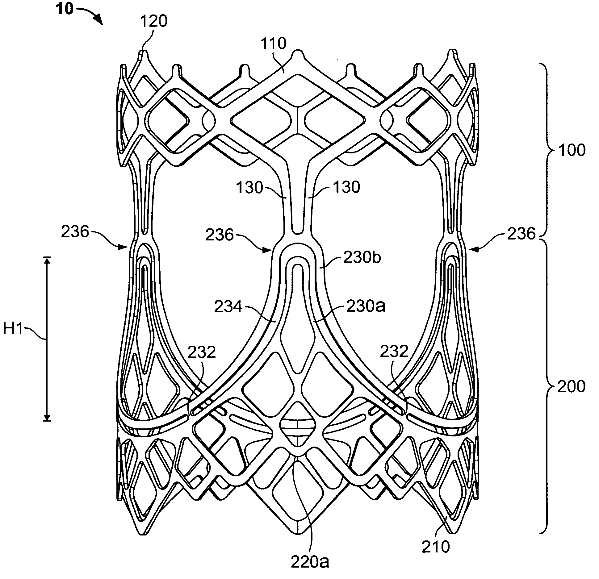
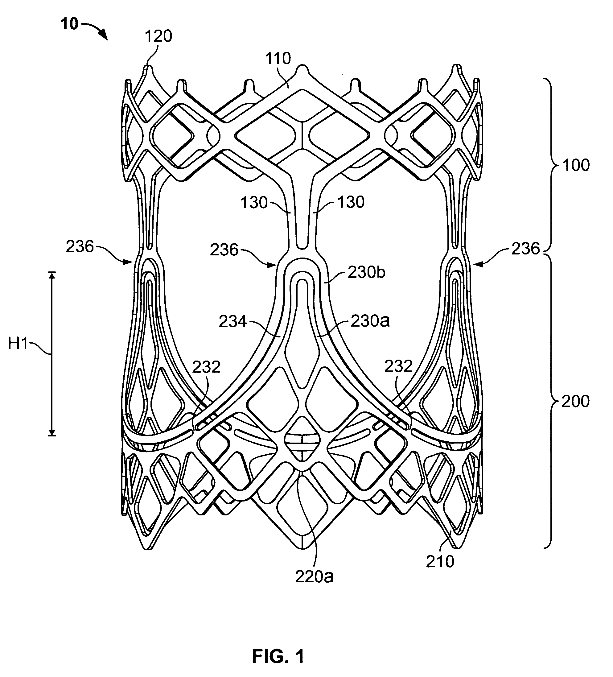
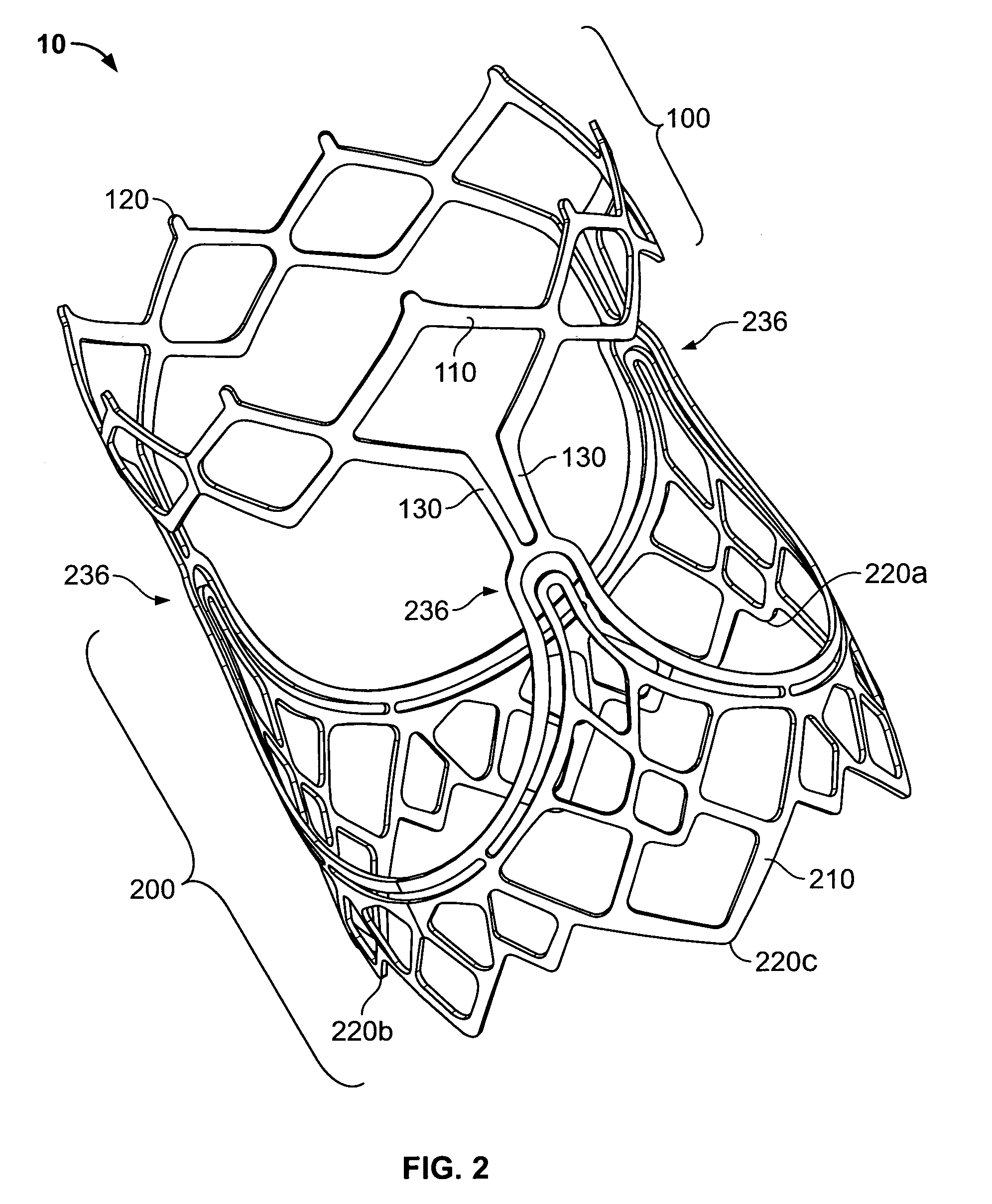
[0049]This detailed description will begin with discussion of an illustrative embodiment of a primary metal component 10 (initially with reference to FIGS. 1-4) that is included in valves in accordance with the invention. Other possible components of a complete valve may be mentioned in this discussion of component 10, but more attention will be given to such possible other components later in this specification. The valves of this invention are collapsible and expandable in the circumferential direction. FIGS. 1-4 and other early FIGS. show illustrative embodiments of these valves (or portions or components of these valves) in their circumferentially expanded condition configuration. Some of the later FIGS. illustrate how valves of this type circumferentially collapse. Alternative terms that may be used for circumferential (in the context of collapse and re-expansion of a valve) include annular (in the sense of ring-like (especially like a closed ring)), diametrical, radial, and th...


PUM


Abstract

A prosthetic heart valve (10) (e.g., a prosthetic aortic valve) is designed to be somewhat circumferentially collapsible and then re-expandable. The collapsed condition may be used for less invasive delivery of the valve into a patient. When the valve reaches the implant site in the patient, it re-expands to normal operating size, and also to engage surrounding tissue of the patient. The valve includes a stent portion (200) and a ring portion (100) that is substantially concentric with the stent portion but downstream from the stent portion in the direction of blood flow through the implanted valve. When the valve is implanted, the stent portion engages the patient's tissue at or near the native valve annulus, while the ring portion engages tissue downstream from the native valve site (e.g., the aorta).

Description

[0001]This application claims the benefit of U.S. provisional patent application 60 / 933,274, filed Jun. 4, 2007, which is hereby incorporated by reference herein in its entirety.BACKGROUND OF THE INVENTION[0002]This invention relates to prosthetic heart valves. For the most part, the invention will be illustratively described in the context of a prosthetic aortic valve that can be temporarily collapsed during a portion of the implantation procedure, and that can be subsequently expanded to its full size at the implantation site. The invention is not necessarily limited to this particular type of use, however, and it will be appreciated that various aspects of the invention can be used in other ways and / or in other contexts.[0003]Many people with severe aortic stenosis go untreated because they are not considered to be suitable candidates for aortic valve replacement using the known prostheses and procedures (e.g., open-chest, open-heart surgery). In an attempt to provide ways of tre...

Claims


Application Information

Patent Timeline
Patent Type & Authority Applications(United States)
IPC IPC(8): A61F2/82A61F2/24
CPCA61F2/2418A61F2220/0075A61F2220/0016A61F2210/0076A61F2230/008A61L27/3604A61L27/54A61F2230/0054
Inventor BRAIDO, PETER N.ALKHATIB, YOUSEF F.
Owner ST JUDE MEDICAL
Why Eureka
Try Eureka