
Intravaginal device with fluid transport plates

a technology of intravaginal device and fluid transport plate, which is applied in the direction of packaging, packaging, packaging, etc., can solve the problems of inability to expand, and inability to immediately absorb fluid by compressed tampon, so as to reduce by-pass leakage and increase the contact area of the absorbent device

Active Publication Date: 2010-07-08
JOHNSON & JOHNSON CONSUMER COPANIES
View PDF98 Cites 31 Cited by
  • Summary
  • Abstract
  • Description
  • Claims
  • Application Information

AI Technical Summary

Benefits of technology

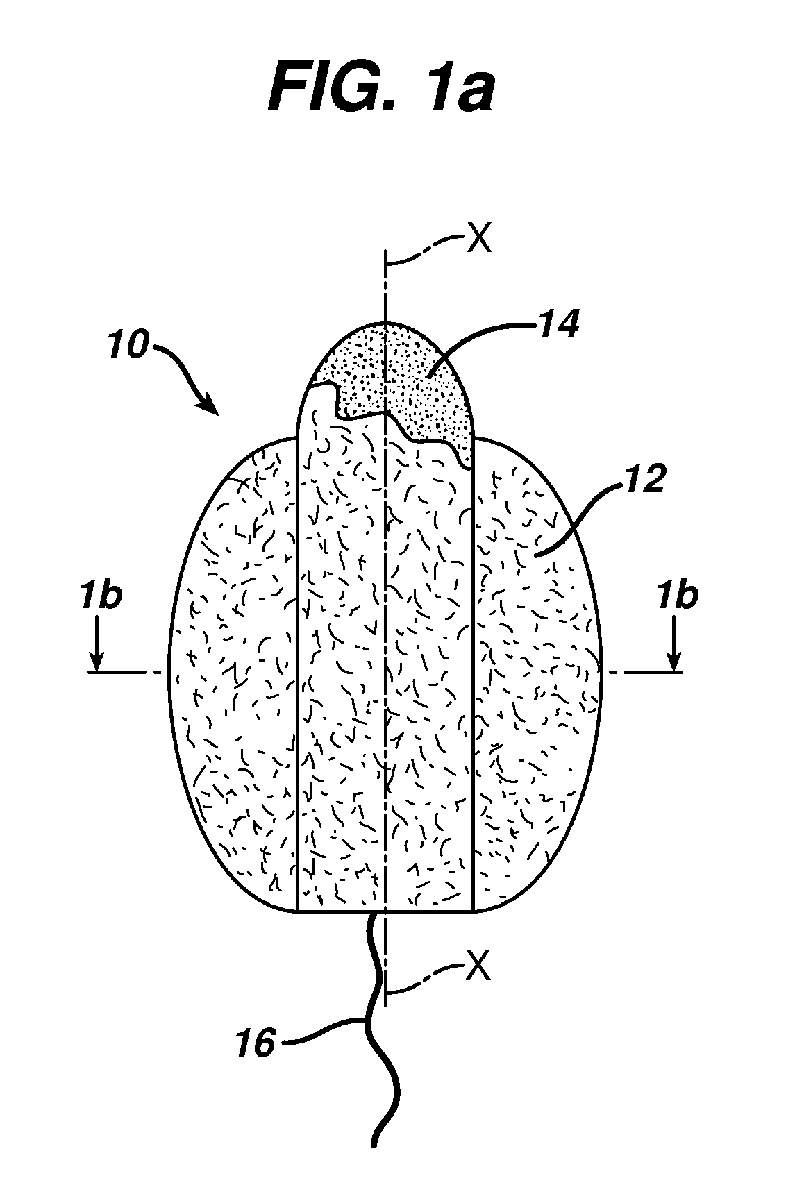
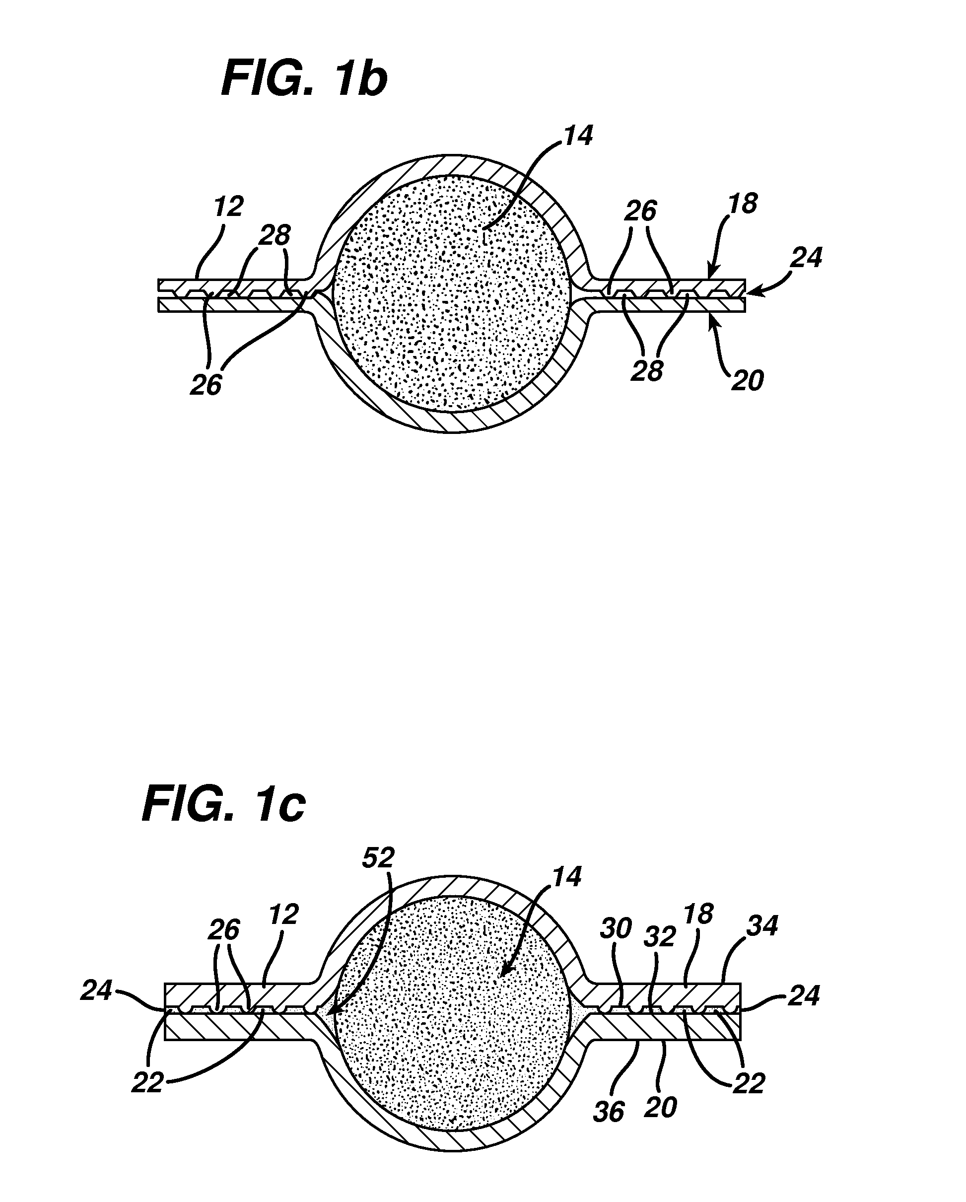
[0015]Surprisingly, we have found a novel way to address the problem of premature failure. This invention is not dependent on the expansion of the compressed absorbent but rather incorporating an element, which is adaptable to the vagina. In our invention, we increase the contact area of the absorbent device and thereby reduce by-pass leakage.

Problems solved by technology

A drawback often encountered with commercially available tampons is the tendency toward premature failure, which may be defined as bodily fluid leakage from the vagina while the tampon is in place, and before the tampon is completely saturated with the bodily fluid.
The patent art typically describes a problem believed to occur that an unexpanded, compressed tampon is unable to immediately absorb fluid.
Therefore, it presumes that premature leakage may occur when bodily fluid contacts a portion of the compressed tampon, and the fluid is not readily absorbed.
While this tampon may allow for a certain amount of protection from bypass leakage, the uncompressed portion may become saturated before the compressed portion has a chance to expand and become absorbent.
The absorbent portions of the tampon can saturate locally, which leads to bypass leakage.
However, based upon current understandings of vaginal pressures, it is not understood how the described structure could form such an opened volume.
Therefore, this external absorbent article can contain fluid gushes, but it does not appear to address the problems relating in particular to intravaginal devices, such as a tampon.
While the prior art is replete with examples of sanitary protection articles that capture bodily fluids both externally and intravaginally, these examples do not overcome the problem of premature failure often identified as by-pass leakage that commonly occurs while using internal sanitary protection devices.

Method used


Image

  • Intravaginal device with fluid transport plates
  • Intravaginal device with fluid transport plates
  • Intravaginal device with fluid transport plates

Examples


Embodiment Construction

[0057]As used herein in the Specification and the Claims, the term “bodily fluid” and variants thereof mean bodily exudates, especially liquids that are produced by, secreted by, emanate from, and / or discharged from a human body.

[0058]As used herein in the Specification and the Claims, the term “fluids” and variants thereof relate to liquids, and especially bodily fluids.

[0059]As used herein in the Specification and the Claims, the term “sheet” and variants thereof relates to a portion of something that is thin in comparison to its length and breadth.

[0060]As used herein in the Specification and the Claims, the term “parallel plate” and variants thereof relates to a system of at least two relatively parallel sheets that are capable of moving fluids through inter-plate capillary action. The individual “plates” in the system may be flexible and / or resilient in order to move within their environment. However, they may be maintained in a substantially facing relationship with relatively...


PUM

PropertyMeasurementUnit
capillary suction pressureaaaaaaaaaa
contact angleaaaaaaaaaa

Abstract

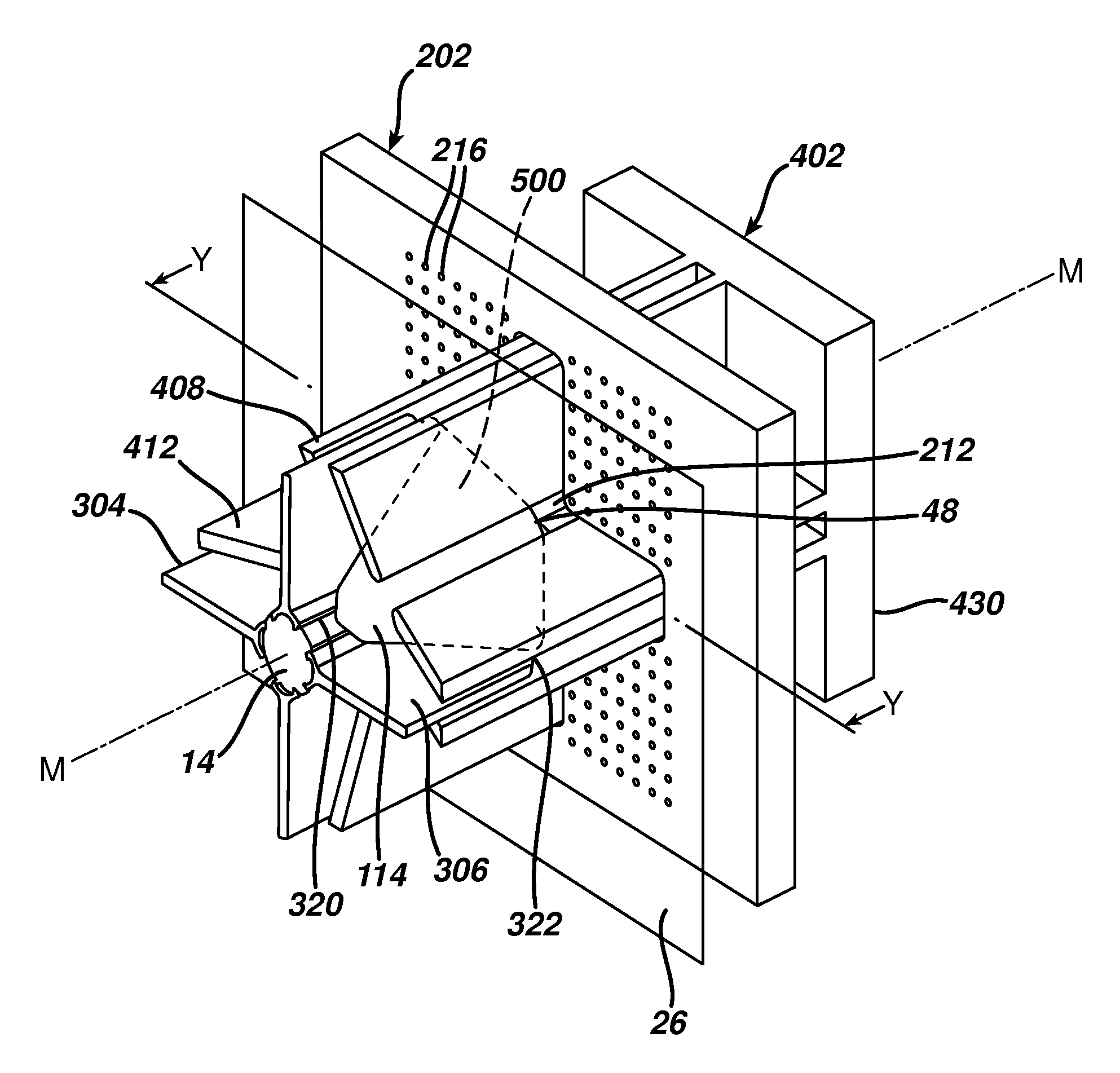
An apparatus for producing an absorbent article includes a holding tool, a female tool disposed along a machine axis, and a male tool disposed along the machine axis. The holding tool has an aperture aligned along the machine axis and means for holding a flexible sheet across the aperture. The female tool has at least one folding element extending in a direction radially away from the machine axis, and the male tool has means for holding a fluid storage element and at least one pleating blade extending in a direction radially away from the machine axis. At least two of the holding tool, female tool, and male tool are capable of relative motion along the machine axis. Further the at least one pleating blade and of the male tool and the at least one folding element of the female tool are aligned to permit manipulation of the flexible sheet about the fluid storage element.

Description

CROSS-REFERENCE TO RELATED APPLICATIONS[0001]This application is a divisional of U.S. application Ser. No. 11 / 478,944, filed on Jun. 30, 2006, which is a continuation-in-part of U.S. application Ser. No. 11 / 444,792, filed on Jun. 1, 2006, and a continuation-in-part of international application PCT / US2005 / 017107 filed May 13, 2005, which claims the benefit of 60 / 572,054 filed on May 14, 2004, and a continuation-in-part of U.S. application Ser. No. 10 / 848,257 filed on May 14, 2004, and a continuation-in-part of U.S. application Ser. No. 10 / 847,951 filed on May 14, 2004, the content of each of which is incorporated herein.[0002]This invention is related to the following applications: U.S. application Ser. No. 10 / 847,952, filed on May 14, 2004 (US publication 2005-0256511-A1), U.S. application Ser. No. 10 / 848,347, filed on May 14, 2004 (US publication 2005-0256485-A1), and U.S. application Ser. No. 10 / 848,208, filed on May 14, 2004 (US publication 2005-0256484-A1), the content of each o...

Claims


Application Information

Patent Timeline
Patent Type & Authority Applications(United States)
IPC IPC(8): D04H1/22B31B1/28A61F13/15A61F13/20B31B50/28
CPCA61F13/2085A61F13/2051B29C66/81463B29C66/8322B29C65/7841B29C66/81423B29C65/18B29C65/7847B29C66/5326B29C66/7485B29C66/71B29C66/21B29C66/843B29C66/7392B29K2067/00B29K2023/00B29K2023/12B29K2023/06B29K2023/083B29K2077/00B29K2075/00B29K2025/06B29K2025/08
Inventor BINNER, CURT
Owner JOHNSON & JOHNSON CONSUMER COPANIES
Learn More