Methods and systems to enhance flame holding in a gas turbine engine

a gas turbine engine and flame-holding technology, applied in the field of gas turbine engines, can solve the problems of increasing the flame-holding margin of the fuel nozzle below the desired allowable limit, poor flame-holding performance, and hot spots or streaks that exceed the local maximum operating temperatur

Inactive Publication Date: 2010-07-08
GENERAL ELECTRIC CO
View PDF13 Cites 23 Cited by
  • Summary
  • Abstract
  • Description
  • Claims
  • Application Information

AI Technical Summary

Problems solved by technology

However, using known methods may decrease flame-holding margins of a fuel nozzle below desired allowable limits for high reactive fuels, such as syngas or high hydrogen fuel.

Method used


Image

  • Methods and systems to enhance flame holding in a gas turbine engine
  • Methods and systems to enhance flame holding in a gas turbine engine
  • Methods and systems to enhance flame holding in a gas turbine engine

Examples


Embodiment Construction

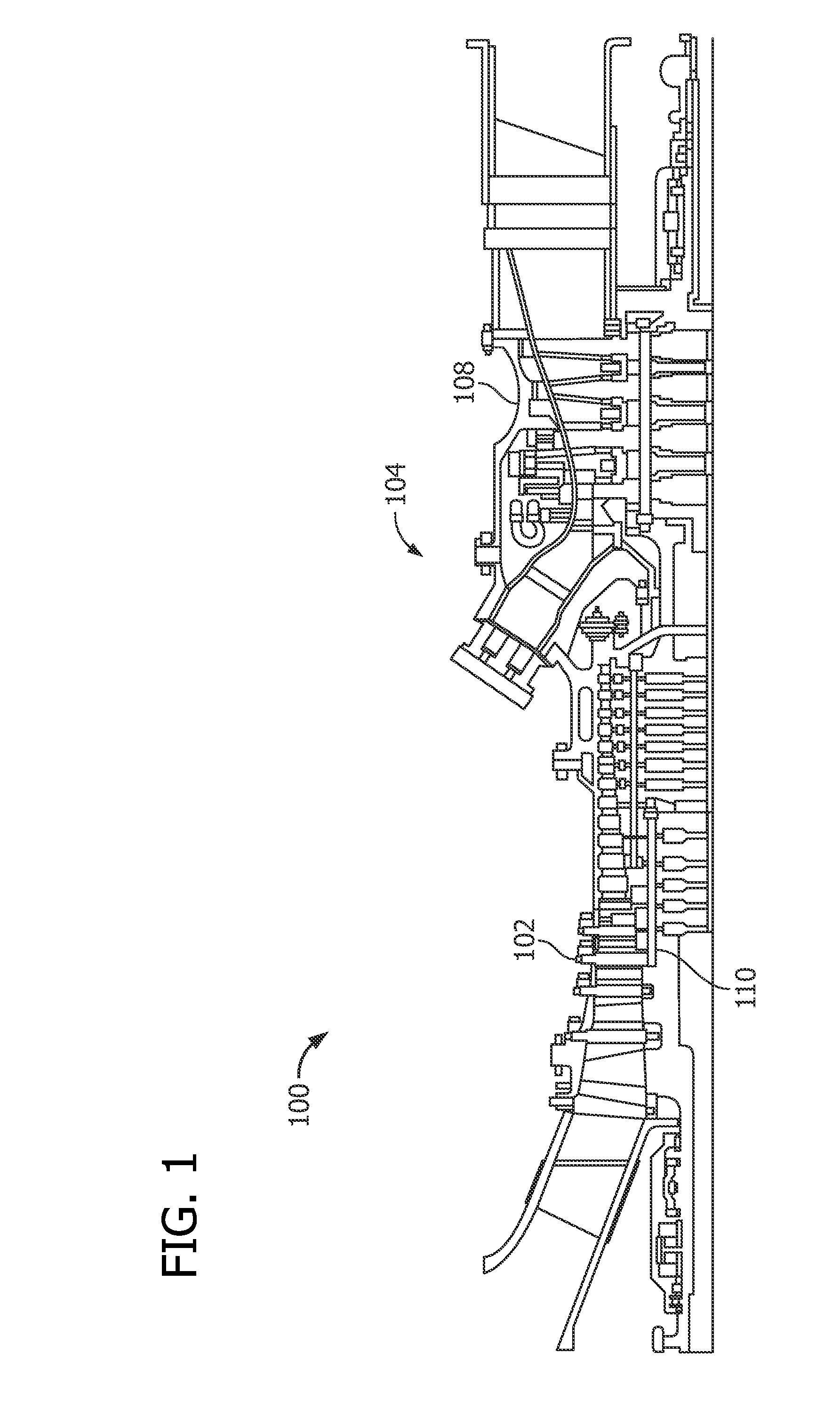
[0015]FIG. 1 is a schematic illustration of an exemplary gas turbine engine 100. Engine 100 includes a compressor 102 and a plurality of circumferentially spaced combustors 104. Engine 100 also includes a turbine 108 and a common compressor / turbine shaft 110 (sometimes referred to as a rotor 110).

[0016]In operation, air flows through compressor 102 such that compressed air is supplied to combustors 104. Fuel is channeled to a combustion region, within combustors 104 wherein the fuel is mixed with the air and ignited. Combustion gases are generated and channeled to turbine 108 wherein gas stream thermal energy is converted to mechanical rotational energy. Turbine 108 is rotatably coupled to, and drives, shaft 110. It should also be appreciated that the term “fluid” as used herein includes any medium or material that flows, including, but not limited to, gas and air.

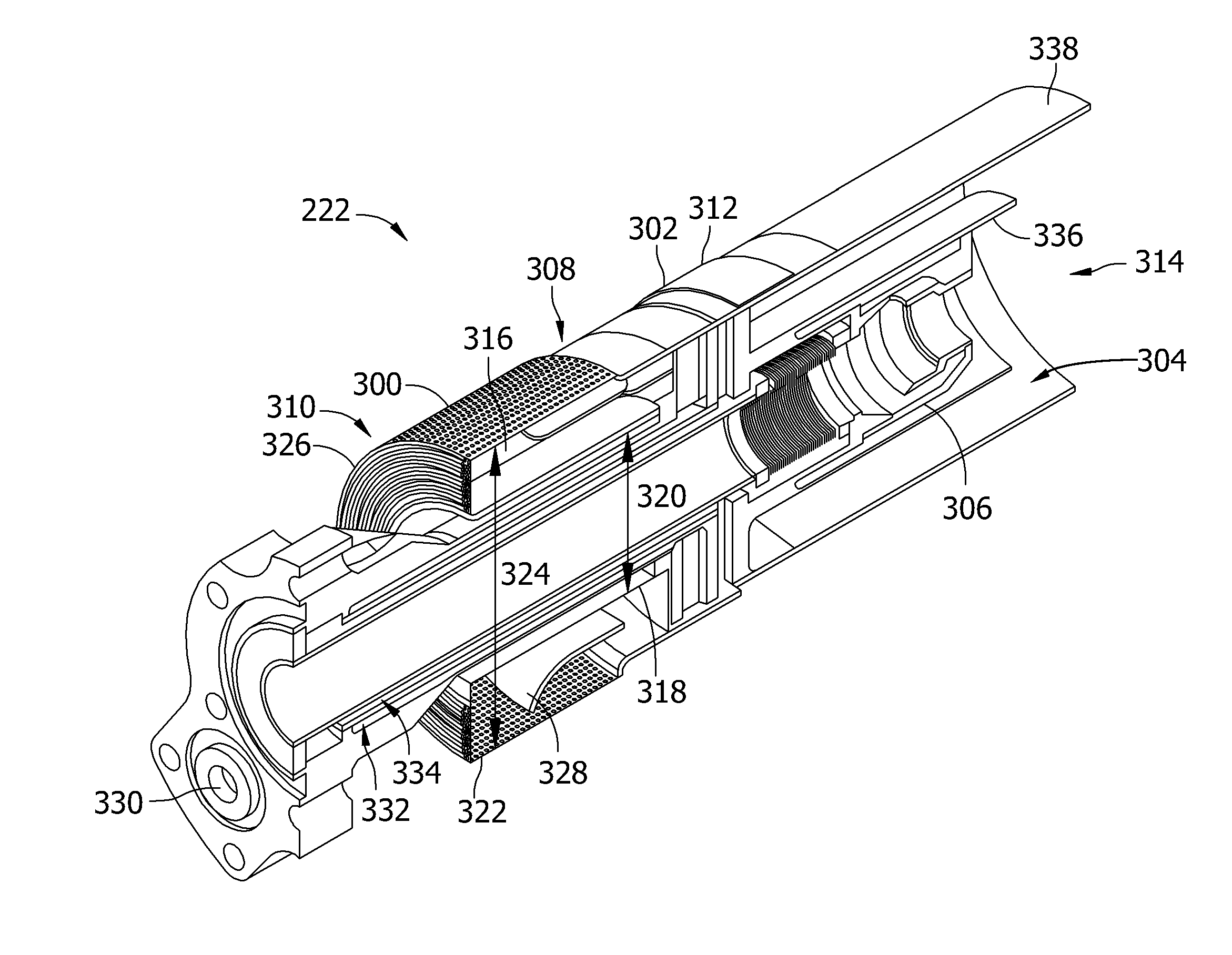
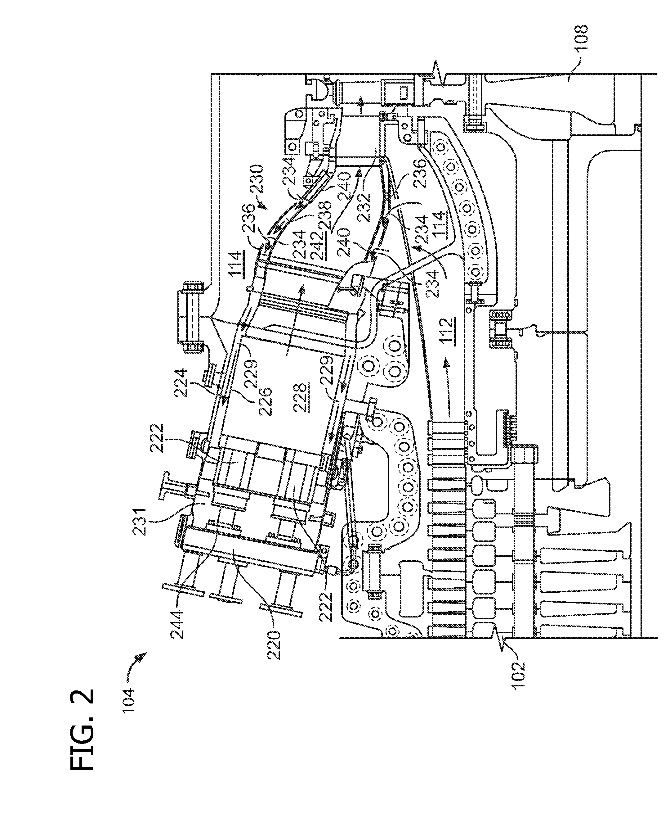
[0017]FIG. 2 is a cross-sectional schematic view of a combustor assembly 104. Combustor assembly 104 is coupled in flow ...


PUM

PropertyMeasurementUnit
Angleaaaaaaaaaa
Pressureaaaaaaaaaa
Heightaaaaaaaaaa

Abstract

A fuel nozzle including a swirler assembly that includes a shroud, a hub, and a plurality of vanes extending between the shroud and the hub. Each vane includes a pressure sidewall and an opposite suction sidewall coupled to the pressure sidewall at a leading edge and at a trailing edge. At least one suction side fuel injection orifice is formed adjacent to the leading edge and extends from a first fuel supply passage to the suction sidewall. A fuel injection angle is oriented with respect to the suction sidewall. The suction side fuel injection orifice is configured to discharge fuel outward from the suction sidewall. At least one pressure side fuel injection orifice extends from a second fuel supply passage to the pressure sidewall and is substantially parallel to the trailing edge. The pressure side fuel injection orifice is configured to discharge fuel tangentially from the trailing edge.

Description

STATEMENT REGARDING FEDERALLY SPONSORED RESEARCH & DEVELOPMENT[0001]This invention was made with Government support under DE-FC26-05NT42643 awarded by the Department of Energy (“DOE”). The Government has certain rights in this invention.BACKGROUND OF THE INVENTION[0002]This disclosure relates generally to gas turbine engines and more particularly, to methods and systems to enhance flame-holding during turbine operation.[0003]At least some gas turbine engines ignite a fuel-air mixture in a combustor to generate a combustion gas stream that is channeled downstream to a turbine via a hot gas path. Compressed air is channeled to the combustor from a compressor. Combustor assemblies typically have fuel nozzles that facilitate fuel and air delivery to a combustion zone defined in the combustor. The turbine converts the thermal energy of the combustion gas stream to mechanical energy that rotates a turbine shaft. The output of the turbine may be used to power a machine, for example, an ele...

Claims


Application Information

Patent Timeline
IPC IPC(8): F02C7/22B23P15/00B05B1/14
CPCF23R3/14F23R3/286Y10T29/49348
Inventor ZUO, BAIFANGLACY, BENJAMIN PAULSTEVENSON, CHRISTIAN XAVIER
Owner GENERAL ELECTRIC CO
Why Eureka
Try Eureka