Sensor element for capacitive differential-pressure sensing

a sensor element and capacitive differential technology, applied in the direction of fluid pressure measurement, pressure difference measurement between multiple valves, instruments, etc., can solve the problems of media to be measured, in particular, not being able to corrode or contaminate electrodes located inside sealed volumes, etc., to improve measurement sensitivity, simplify signal analysis, and minimize offset errors

Active Publication Date: 2010-07-08
ROBERT BOSCH GMBH
View PDF9 Cites 19 Cited by
  • Summary
  • Abstract
  • Description
  • Claims
  • Application Information

AI Technical Summary

Benefits of technology

[0010]On the whole, it proves to be advantageous, in terms of providing the smallest possible lateral dimensions of the sensor structure, when the fixed support structure is configured between the two diaphragms of the diaphragm structure.
[0011]In a first variant of the sensor element according to the present invention, the at least one deflectable electrode may then be configured in the middle region of a diaphragm of the dual-diaphragm structure. This middle region of the diaphragm is advantageously stiffened, so that diaphragm deformations preferably occur in the flexurally soft peripheral region of the diaphragm, and the electrode itself is not deformed upon deflection of the diaphragm structure. This measure is directed to minimizing offset errors and to simplifying the signal analysis.
[0012]In contrast, in a second variant of the sensor element according to the present invention, the dual-diaphragm structure includes a support plate specifically for the at least one deflectable electrode. This support plate is located between the two diaphragms and is rigidly joined thereto via the at least one connecting crosspiece between the two diaphragms. The support plate, together with the diaphragm structure, is thereby deflected relative to the fixed support structure provided for the at least one fixed electrode. In this variant, the two diaphragms of the diaphragm structure may be designed to be thin and flexurally soft over the entire surface thereof, thereby enhancing the measuring sensitivity without impeding the signal analysis. In this case, the diaphragm deformations have the sole effect of deflecting the support plate together with the deflectable electrode, not, h

Problems solved by technology

The media to be measured, in particular, are not able to corrode

Method used


Image

  • Sensor element for capacitive differential-pressure sensing
  • Sensor element for capacitive differential-pressure sensing
  • Sensor element for capacitive differential-pressure sensing

Examples


Embodiment Construction

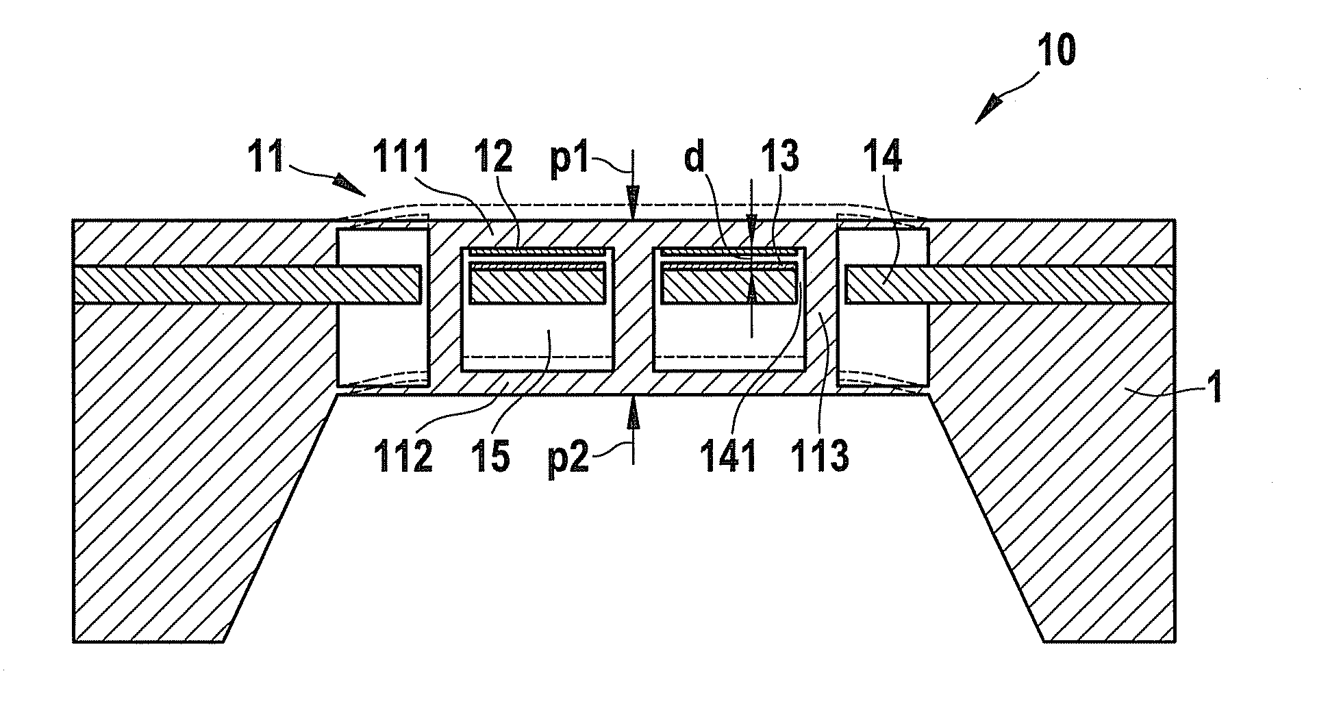
[0020]Micromechanical sensor element 10, illustrated in FIG. 1, for capacitive differential pressure sensing includes a diaphragm structure 11, which is implemented in accordance with the present invention in the form of a dual diaphragm having two mutually parallel disposed diaphragms 111 and 112. In the exemplary embodiment shown here, these two diaphragms 111 and 112 are rigidly interconnected via three connecting crosspieces 113, so that each application of force to one of the two diaphragms 111 or 112 is directly transmitted to the respective other diaphragm 112 or 111. The one diaphragm 111 of diaphragm structure 11 is pressurized by a first medium to be measured, i.e., by a first measuring pressure p1 emanating from the front side of sensor element 10, while the other diaphragm 112 is pressurized by a second medium to be measured, i.e., by a second measuring pressure p2 emanating from the rear side of sensor element 10. Altogether, therefore, pressure differential Δp=p1−p2 ac...


PUM


Abstract

A sensor design, respectively a micromechanical sensor structure for capacitive relative-pressure measurement, that will allow very small pressure differentials to be reliably recorded at high absolute pressures even in harsh, particle-laden measuring environments. For that purpose, the micromechanical sensor element includes a deflectable diaphragm structure which is provided with at least one deflectable electrode, and a fixed support structure for at least one fixed counter-electrode which is located opposite the deflectable electrode. The diaphragm structure includes two mutually parallel configured diaphragms that are joined rigidly to one another via at least one connecting crosspiece, so that each application of force to one of the two diaphragms is directly transmitted to the respective other diaphragm. The first diaphragm is able to be pressurized by a first measuring pressure emanating from the front side of the sensor element, and the second diaphragm is able to be pressurized by a second measuring pressure emanating from the rear side of the sensor element. The fixed counter-electrode is located in the sealed volume between the two diaphragms of the diaphragm structure.

Description

FIELD OF THE INVENTION[0001]The present invention relates to a micromechanical sensor element for capacitive differential pressure sensing, having a deflectable diaphragm structure which is provided with at least one deflectable electrode, and having a fixed support structure for at least one fixed counter-electrode which is located opposite the deflectable electrode.BACKGROUND INFORMATION[0002]Pressure sensors equipped with micromechanical sensor elements are used today in machine manufacturing, process technology, automotive engineering, and in medical technology for many diverse measuring tasks. Differential-pressure sensors are used for comparing pressures that prevail in spaces or media that are separated from one another. The media to be measured can be liquids, gases or also vapors.[0003]In automotive engineering, a typical application of micromechanical differential-pressure sensors is to compare the exhaust back pressure upstream and downstream of the particulate filter. Si...

Claims


Application Information

Patent Timeline
IPC IPC(8): G01L9/12
CPCB81B3/0078B81B2201/0264G01L9/0072G01L13/025
Inventor OPITZ, BERNHARDDOERING, CHRISTIANARTMANN, HANSWOLFF, JANPETERNIEKRAWIETZ, REMIGIUS
Owner ROBERT BOSCH GMBH
Why Eureka
Try Eureka