
Multi purpose vehicle furniture system

a vehicle furniture and multi-purpose technology, applied in the direction of convertible stools, chairs, transportation and packaging, etc., can solve the problems of not being able to utilize a primary support, prior art vehicle furniture systems are not suitable in the space, and furniture systems are not suitable, so as to facilitate the course of a trip, not having to sacrifice added time and expense, and being convenient to deploy

Inactive Publication Date: 2010-07-08
DUNKEL PETER L
View PDF8 Cites 8 Cited by
  • Summary
  • Abstract
  • Description
  • Claims
  • Application Information

AI Technical Summary

Benefits of technology

[0010]The prior art vehicle furniture systems appear to be intended for recreational vehicles where there is abundant space for separate furniture fixtures for each of eating, sleeping, and sitting functions. Accordingly, these prior art systems are not suitable in the space constrained area proximate to the driver's seat in a commercial cargo truck or a pick-up truck. None of these prior art vehicle furniture systems appear to utilize a primary support that is rotatably and slidably engaged to a first post. Nor do these prior art vehicle furniture systems appear to be capable of assuming different positions based on the angle of rotation between the primary support top surface or the primary support bottom surface and the floor. These prior art vehicle furniture systems appear to be bulkier both in size and weight as compared with the multi-purpose vehicle furniture system. As such, the added weight of these prior art vehicle furniture systems results in a diminished fuel efficiency, thereby adding to fuel costs. Also, due to their added size, these prior art vehicle furniture systems result in greater material costs. The prior art vehicle furniture systems also appear to be more difficult to install, due to their apparent use of bulky and / or cumbersome parts, thereby potentially necessitating the driver to receive assistance in their installation.
[0014]This feature of the vehicle furniture system is innovative in that it enables the primary support to be axially rotatable about the primary support rod, thereby enabling the primary support to be conveniently converted from the first, second, third, and fourth positions, as the angle between the primary support top surface or the primary support bottom surface and the floor is modified.
[0017]This feature of the vehicle furniture system is innovative in that it enables the primary support to be axially rotatable about the primary support rod and readily engageable into one of the first position, the second position, the third position, or the fourth position. This in turn allows the vehicle furniture system to be conveniently and efficiently converted into and between the table top, bed, or seat modes. As a result, the vehicle furniture system can be assembled into its various positions by a single user, without the need for assistance from others.

Problems solved by technology

Accordingly, these prior art systems are not suitable in the space constrained area proximate to the driver's seat in a commercial cargo truck or a pick-up truck.
None of these prior art vehicle furniture systems appear to utilize a primary support that is rotatably and slidably engaged to a first post.
Nor do these prior art vehicle furniture systems appear to be capable of assuming different positions based on the angle of rotation between the primary support top surface or the primary support bottom surface and the floor.
These prior art vehicle furniture systems appear to be bulkier both in size and weight as compared with the multi-purpose vehicle furniture system.
As such, the added weight of these prior art vehicle furniture systems results in a diminished fuel efficiency, thereby adding to fuel costs.
Also, due to their added size, these prior art vehicle furniture systems result in greater material costs.
The prior art vehicle furniture systems also appear to be more difficult to install, due to their apparent use of bulky and / or cumbersome parts, thereby potentially necessitating the driver to receive assistance in their installation.

Method used


Image

  • Multi purpose vehicle furniture system
  • Multi purpose vehicle furniture system
  • Multi purpose vehicle furniture system

Examples


Embodiment Construction

[0039]The drawings referred to herein are for the purposes of illustrating the preferred embodiments of the present invention and not for the purposes of limiting the same.

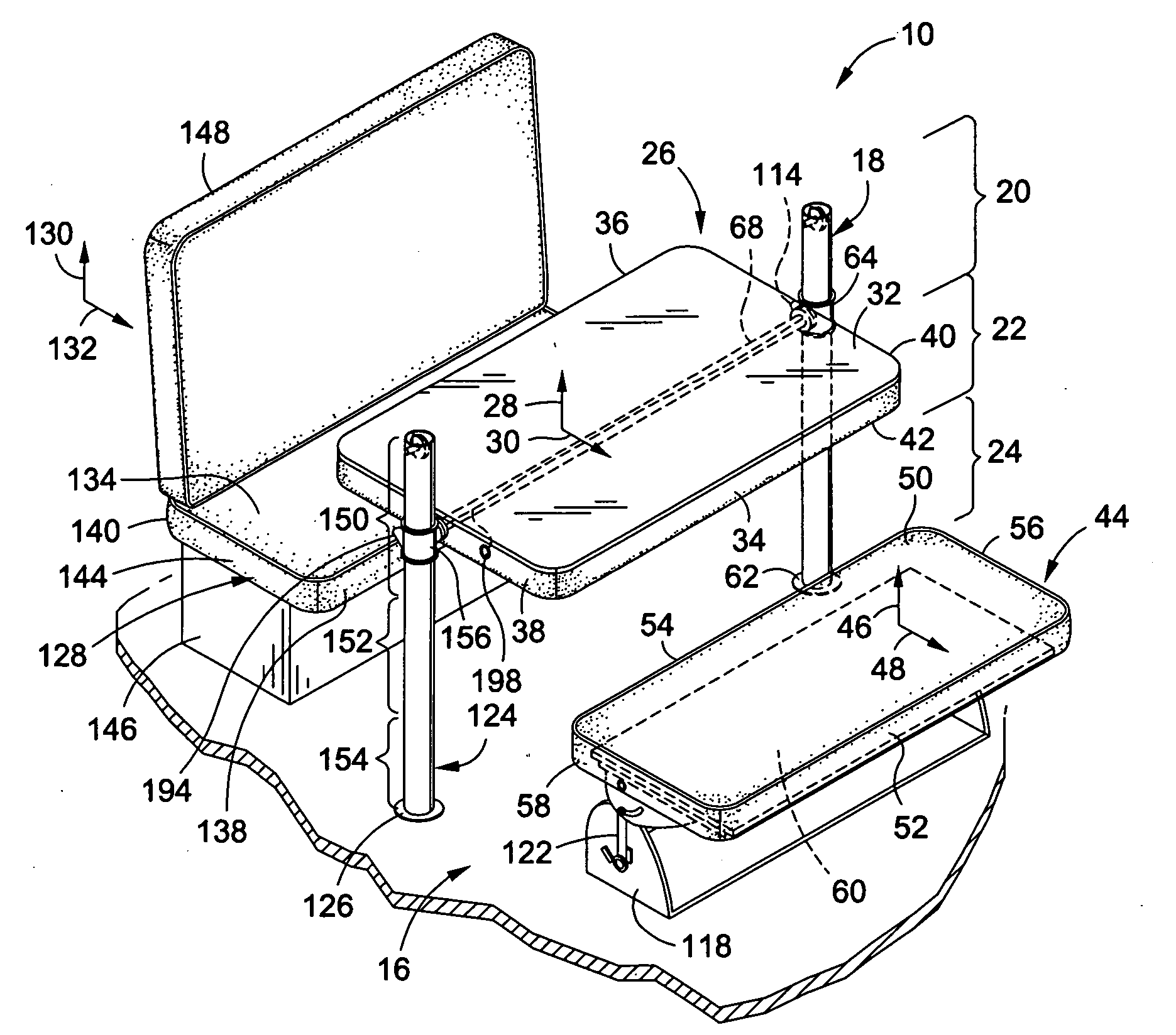
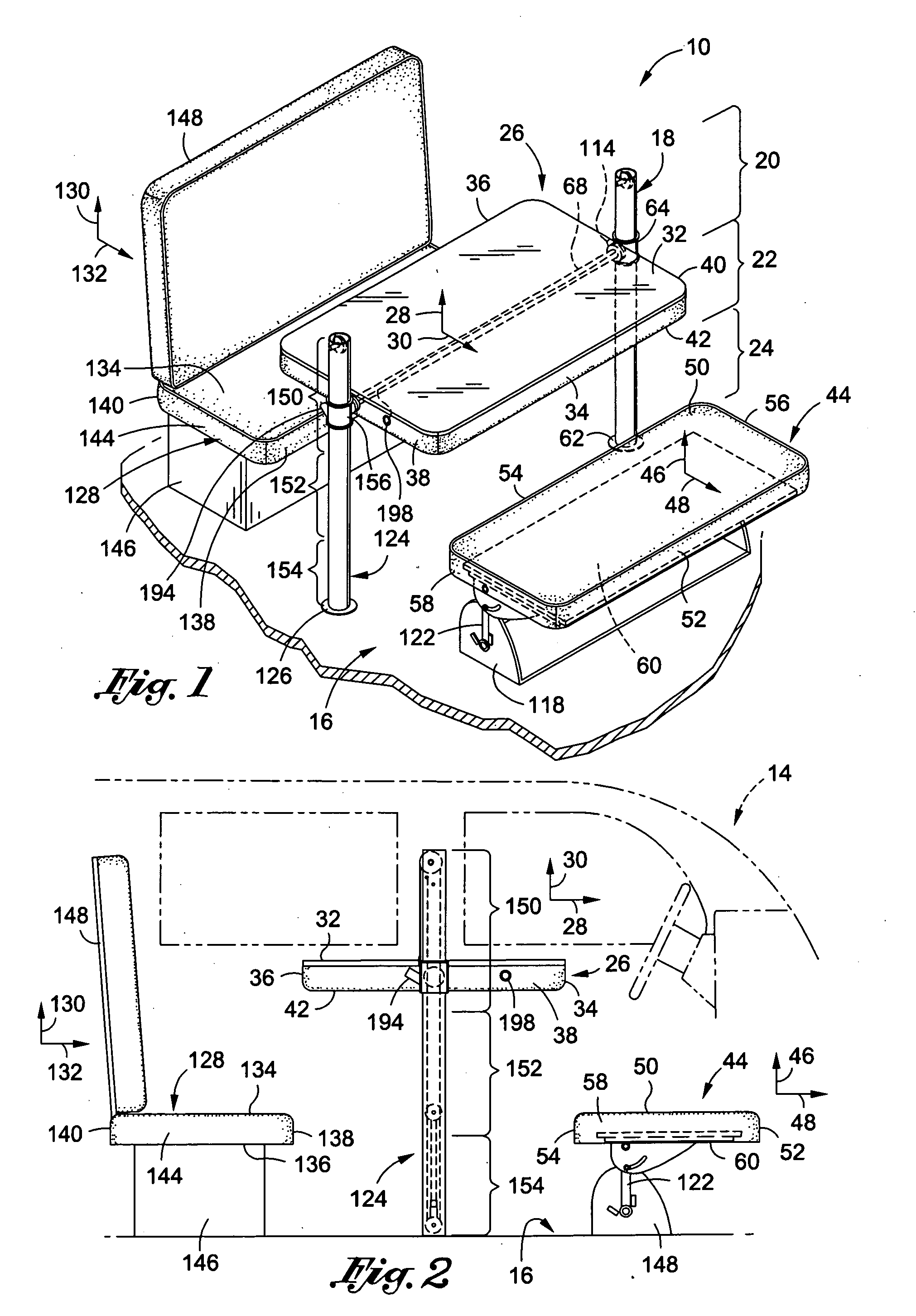
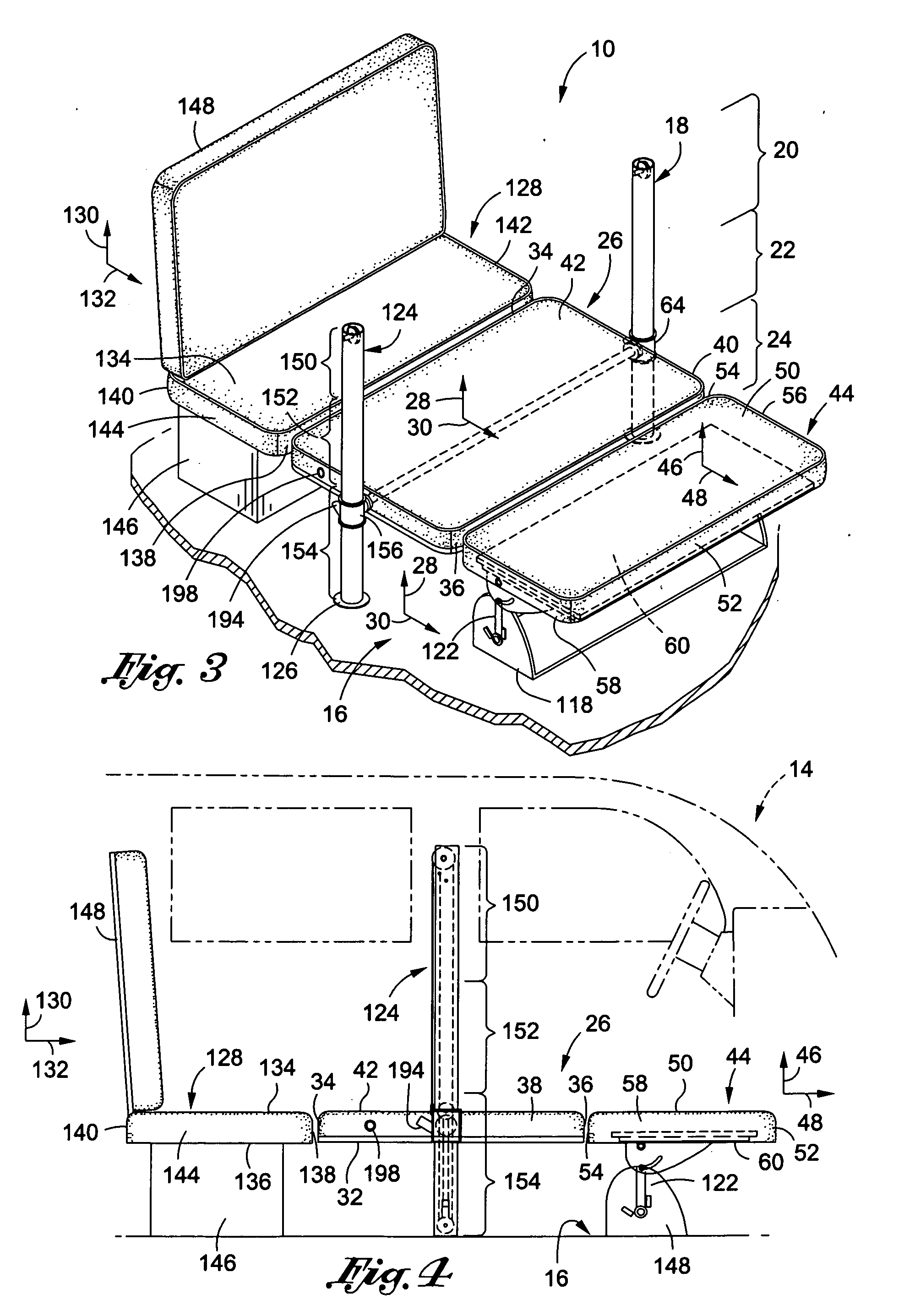
[0040]FIG. 1 is an embodiment of a multi-purpose vehicle furniture system 10 mountable to a floor 16 of a vehicle 14. A primary support 26 may be rotatably and slidably engaged to a first post 18. The primary support 26 may define a primary support longitudinal axis 28 and a primary support lateral axis 30 disposed perpendicular to the primary support longitudinal axis 28. The primary support 26 may have a primary support top surface 32 and an opposing primary support bottom surface 42. The primary support 26 may also have a primary support first longitudinal side 34, a primary support second longitudinal side 36, a primary support first lateral side 38, and a primary support second lateral side 40. The primary support first lateral side 38 and the primary support second lateral side 40 may be disposed generally b...


PUM


Abstract

A vehicle furniture system for use proximate to a vehicle driver's seat, the system comprising: a first post having a first post first end, a first post body, and a first post second end mountable to the floor of the vehicle; a primary support having a primary support longitudinal axis generally perpendicular to a primary support lateral axis, a primary support top surface, a primary support bottom surface, a primary support first longitudinal side rotatably and slidably engageable to the first post, a primary support second longitudinal side, a primary support first lateral side, and a primary support second lateral side, the primary support disposable in a first position, a second position, a third position, and a fourth position; a primary support rod; and a second support adjacent to the primary support with the primary support in the second position and the third position.

Description

CROSS-REFERENCE TO RELATED APPLICATIONS[0001]Not ApplicableSTATEMENT RE: FEDERALLY SPONSORED RESEARCH / DEVELOPMENT[0002]Not ApplicableBACKGROUND[0003]The present invention relates generally to a multi-purpose vehicle furniture system for use proximate to a driver's seat in most transport vehicles, such as a commercial cargo truck or pick-up truck.[0004]Recreational vehicles and trailers are known to have fixtures for comfortably sleeping, seating, and providing an eating area for its passengers. Commercial cargo trucks and pick-up trucks on the other hand, due to space constraints, have far fewer options in providing their passengers with dining, seating and bedding accommodations. Commercial cargo trucks may provide for a small sleeping quarters above the cab. However, this “overhang” space is typically far too small to accommodate a table for dining or a chair for sitting.[0005]Drivers of pick-up trucks or commercial cargo trucks are often forced to interrupt lengthy road trips to ...

Claims


Application Information

Patent Timeline
Patent Type & Authority Applications(United States)
IPC IPC(8): A47C13/00
CPCB60N2/206B60N2/3013B60N2/3027B60N2/3031B60N2/995B60N2/32B60N2/34B60N3/001B60N2/3065
Inventor DUNKEL, PETER L.
Owner DUNKEL PETER L
Learn More