
Liquid jet recording head and manufacturing method thereof

Active Publication Date: 2010-07-08
CANON KK
View PDF5 Cites 37 Cited by
  • Summary
  • Abstract
  • Description
  • Claims
  • Application Information

AI Technical Summary

Benefits of technology

[0047]The present invention is directed to preventing a droplet from failing to be discharged even if a bubble gets into a recording liquid supply path.
[0050]Furthermore, the present invention is directed to decreasing a recording head in size, realizing both of preventing the bubble from getting into the recording liquid supply path, and securing a cross-section area of the recording liquid supply path.
[0053]According to the present invention, a void portion is not provided at a bonding section between two members which forms the recording liquid supply path, and thus bubbles staying in the recording liquid supply path is decreased to smoothly supply the recording liquid. Accordingly, an easy suction operation and suction processing with low frequency can be sufficiently performed as an operation of suction recovery for removing the bubbles.
[0054]Further, the following arrangements can decrease a size of the recording head by decreasing a distance between the adjacent flow paths.
[0058]4) Since the cross section of the recording liquid supply path has a substantially-rectangular shape, the large cross-section area of the flow path can be secured.

Problems solved by technology

If the above-described bubbles gather in the common liquid chamber and stay there to grow into a large bubble, defective supplying of the recording liquid can occur.
Furthermore, if the defective supplying worsens and spreads in a wide range, the droplets cannot be discharged.
If the recording liquid is hindered from being supplied, eventually the droplet is not discharged due to defective supplying of the recording liquid.
Further, even if the droplet is not completely obstructed by the bubble, in a recording mode in which a large amount of recording liquid needs to be supplied, defective discharging of the droplet can occur in a wide range.
1) Due to fusion bonding of two members (liquid path forming member and container holding member), fused resin can get into the recording liquid supply path to form a burr shape and protrusion therein.
2) Further, the protruding resin in a burr shape comes off due to ultrasonic wave vibration and becomes broken pieces, which can scatter in the recording liquid supply path.
3) After the two members are bonded with each other, an inside of the recording liquid supply path needs to be cleaned to remove the burr and the broken pieces.
4) To decrease the protruding of the fused resin, between a raised portion serving as the bonding section of the two members and also as the energy director, and an recessed portion used as the clearance groove into which the raised portion is inserted, a void for containing the fused resin needs to be provided.
5) Since the bubble stays in the void, suction recovery is necessary to remove the staying bubble.
6) A high accuracy of flatness is required of both bonding surfaces of the flow path forming member and the container holding member.
1) If the upper portion of the supply path is formed in an arc shape, a cross-section area of the flow path becomes small, which gives the structure a disadvantage in decreasing size of the recording head.
5) If the adhesive 2004 comes out, wettability inside the flow path cannot be uniform, thus deteriorating a performance in supplying the recording liquid.
6) Since a wall between the adjacent flow paths is formed to have an nonuniform thickness such that the wall becomes thicker toward the upper portion of the flow path, a sink mark can occur when the member is injection molded, thereby deteriorating a dimension accuracy.
More specifically, a region having a thick member decreases the laser transmission rate compared to a region having a thin member, thereby decreasing a welding strength.
Thus, the distribution of energy of the laser irradiation is deteriorated, and a desired welding strength cannot be obtained.
If a large curve or a large sink mark is generated on the bonding surfaces, adhesiveness between the container holding member and the flow path forming member is deteriorated.
As described in the above three conventional cases, the bubble remaining in the recording liquid supply path may disturb the recording liquid to be supplied.
Further, if the bubble grows into a larger bubble, the flow of the recording liquid is disturbed.
The recording liquid is not sufficiently supplied into a nozzle, so that the droplet is not discharged.
When the fusion bonding generates the protrusion or a burr into the recording liquid supply path, similarly to the bubble, the protrusion or the burr disturbs the recording liquid to be supplied and causes the droplet not to be discharged.
Further, in the laser welding method, changing the thickness of the member and providing the protrusion and the slope that may disturb the laser transmission are restricted.

Method used


Image

  • Liquid jet recording head and manufacturing method thereof
  • Liquid jet recording head and manufacturing method thereof
  • Liquid jet recording head and manufacturing method thereof

Examples


Embodiment Construction

[0081]Various exemplary embodiments, features, and aspects of the invention will be described in detail below with reference to the drawings.

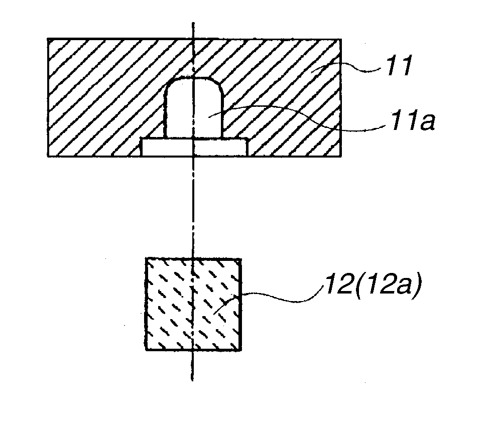
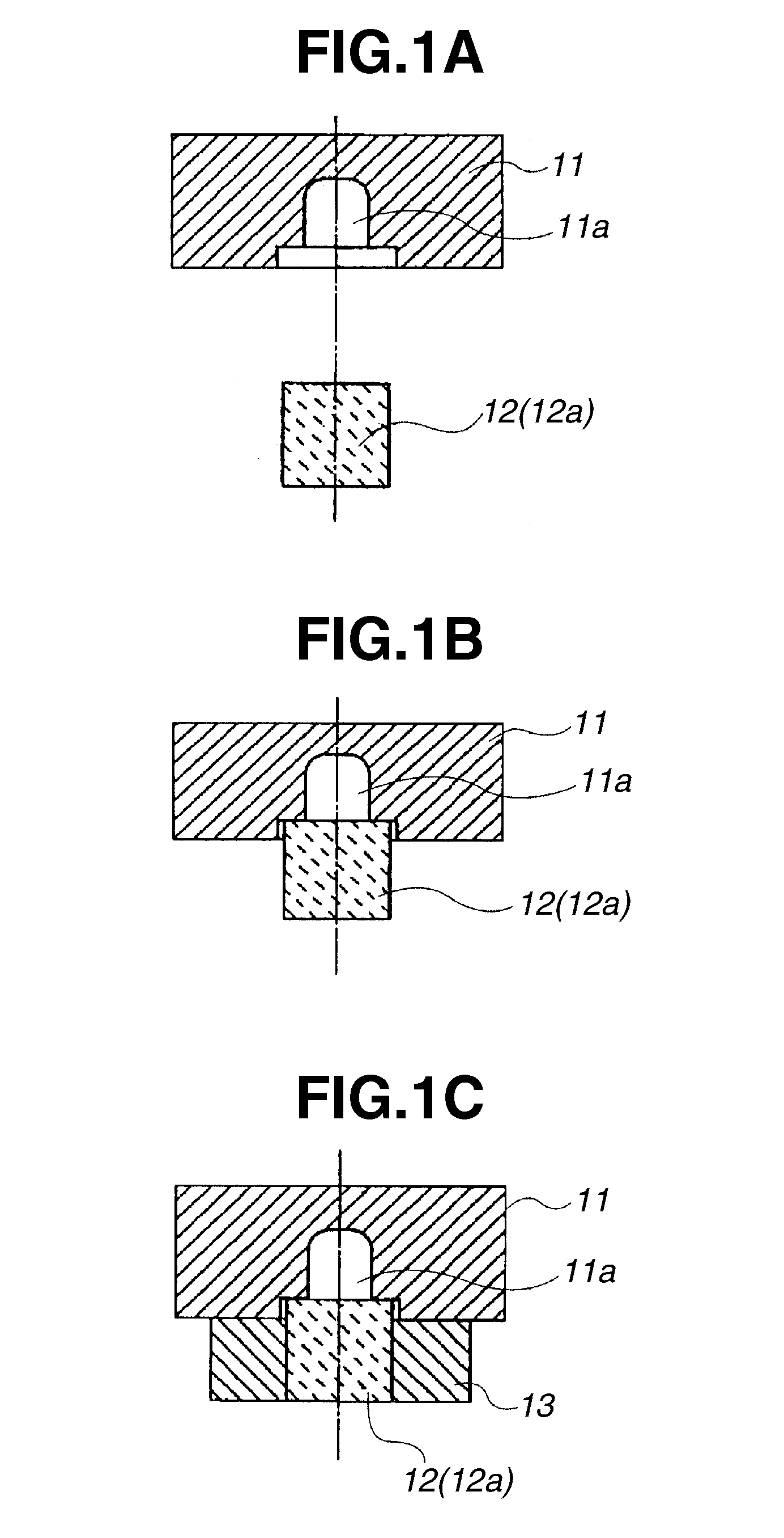
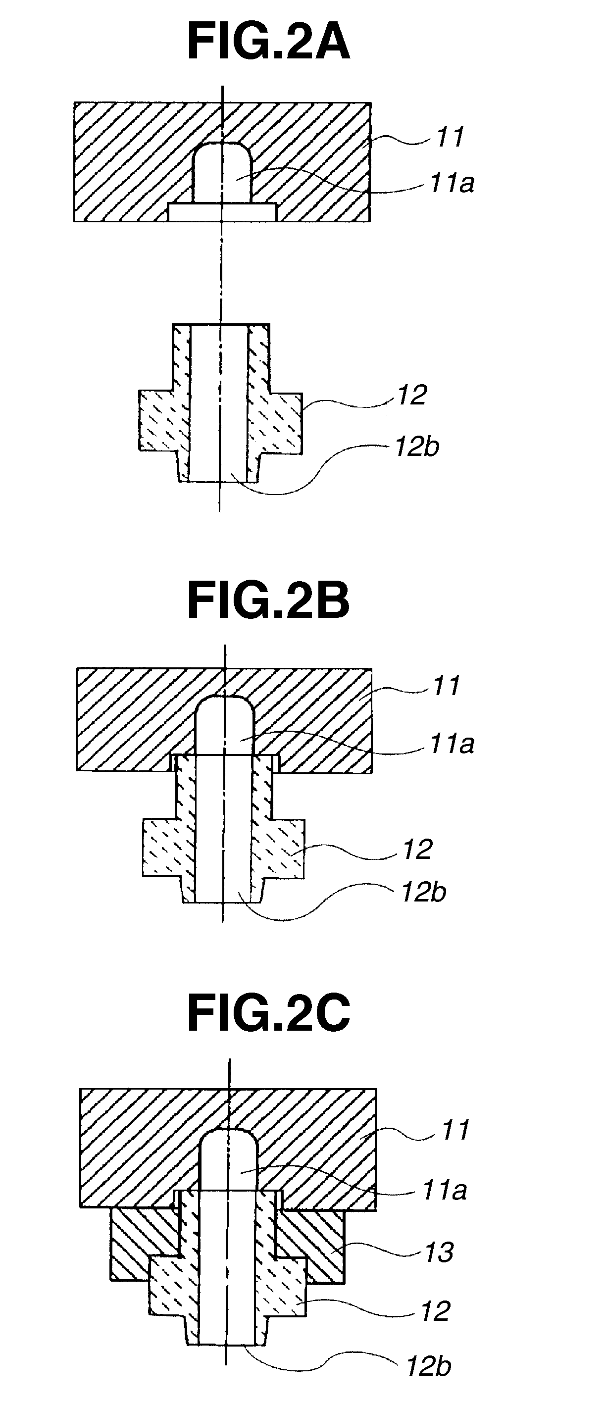
[0082]FIGS. 1A, 1B, and 1C are cross-sectional views illustrating a half way supply path in an example of a structure of a recording liquid supply path in a liquid jet recording head according to the present invention. FIGS. 2A, 2B, and 2C are cross-sectional views illustrating an outlet port of the supply path in the example of the structure of the recording liquid supply path, which is the same example as those in FIGS. 1A, 1B, and 1C.

[0083]As illustrated in FIGS. 1A, 1B, and 1C and FIGS. 2A, 2B, and 2C, a recording liquid supply path 11a is formed by bonding a primary flow path forming member 11 and a second flow path forming member 12. The second flow path forming member 12 is bonded to the primary flow path forming member 11 with a bonding member 13. The second flow path forming member 12 is provided with a 12b for leading the recording li...


PUM

PropertyMeasurementUnit
Widthaaaaaaaaaa
Widthaaaaaaaaaa
Widthaaaaaaaaaa

Abstract

A primary flow path forming member is provided with a groove which becomes a recording liquid supply path on a bottom surface thereof. A second flow path forming member is provided with an arm portion having a small width and a large length. The arm portion of the second flow path forming member is used as a cap for closing the opening of the groove which becomes the liquid supply path formed on the bottom surface of the prime flow path forming member. The primary flow path forming member and the second flow path forming member as described above are formed by injection-molding and bonded with each other by a bonding member. The bonding member is formed to cover the periphery of a portion where the opening edge of the groove which becomes the recording liquid supply path, in the primary flow path forming member abuts on the arm portion of the second flow path forming member.

Description

BACKGROUND OF THE INVENTION[0001]1. Field of the Invention[0002]The present invention relates to a liquid jet recording head which performs recording by jetting droplets such as recording liquid from a discharge port to a recording medium such as paper and cloth, and a liquid jet recording apparatus which uses the liquid jet recording head, or a manufacturing method of the liquid jet recording head.[0003]2. Description of the Related Art[0004]Such a liquid jet recording apparatus features a recording head which can be easily decreased in size. Further, the apparatus can record a highly fined image at high speed and can decrease running costs and reduce noise since the apparatus is a non impact-printer. Furthermore, the apparatus has many advantages, for example, the apparatus can easily record a color image by using multicolor recording liquid.[0005]The liquid jet recording head includes a recording head which forms the droplets, and a recording liquid supply unit which supplies the...

Claims


Application Information

Patent Timeline
IPC IPC(8): B41J2/175
CPCB41J2/16532B41J2/17513B29C2045/0063B29C2045/1637
Inventor YAMAGUCHI, YUKUOKIMURA, SATOSHI
Owner CANON KK
Learn More