

Rear-view display system for a bicycle
- Summary
- Abstract
- Description
- Claims
- Application Information
AI Technical Summary
Benefits of technology
Problems solved by technology
Method used
Image

Examples
first embodiment
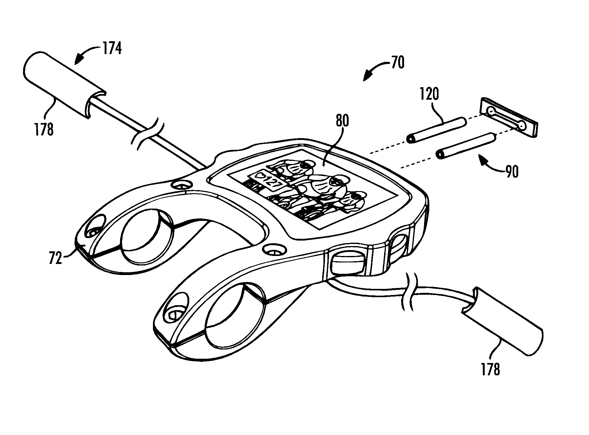
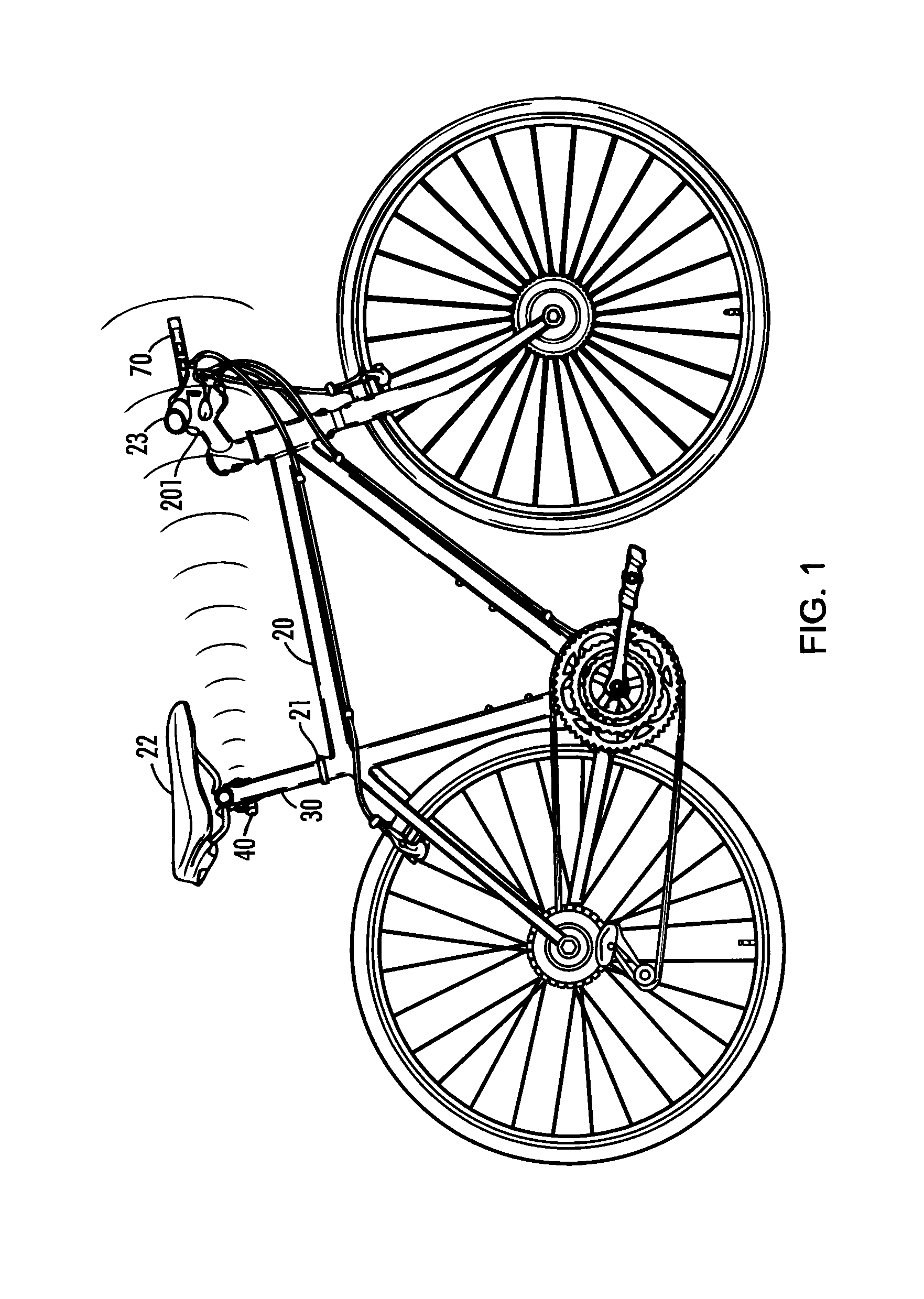
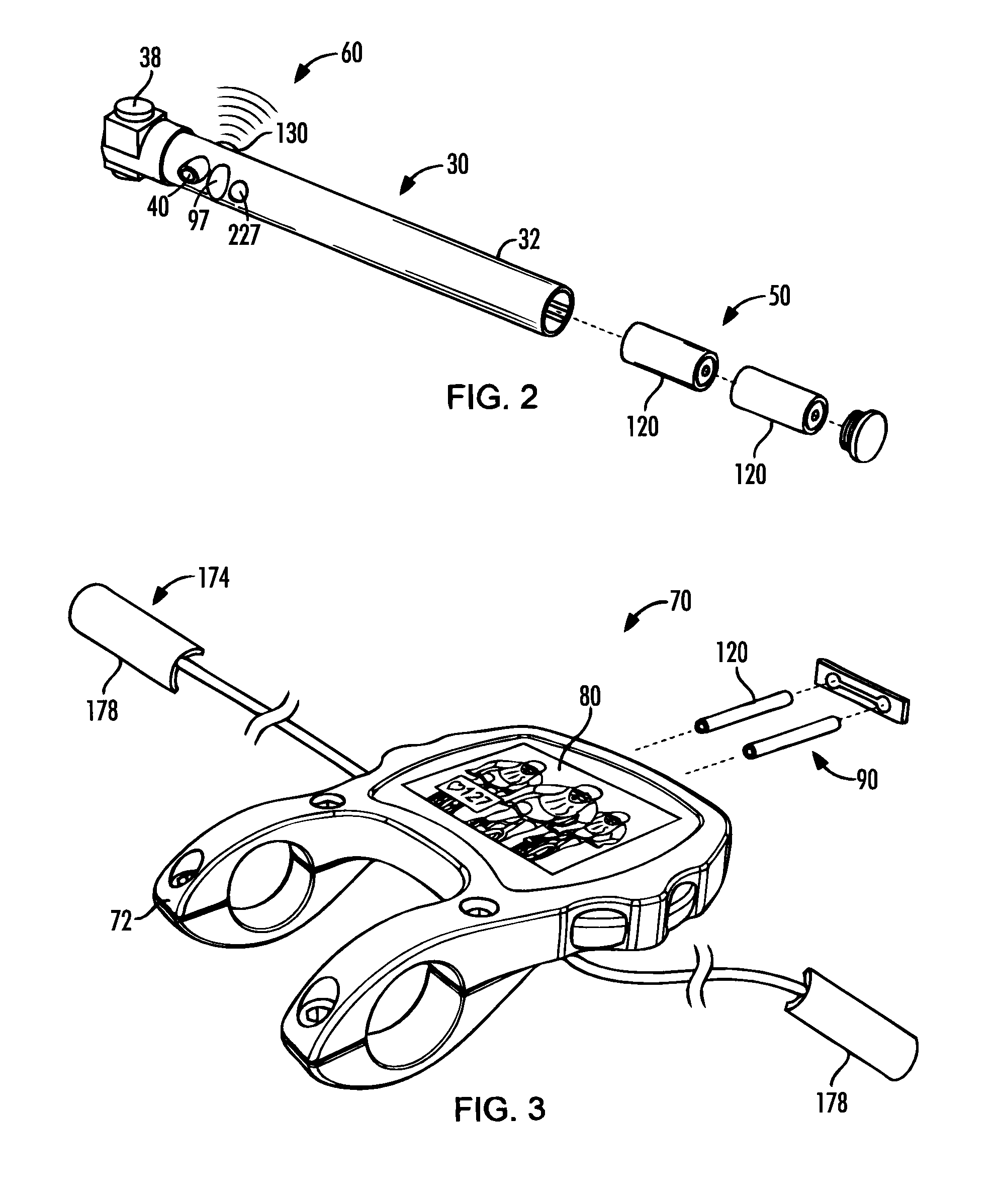
[0029]In the invention, illustrated in FIGS. 1 and 6, the signaling means 60 is a wireless signaling means 130, such as a radio or infrared signaling transmitter 180 utilizing Garmin's ANT+Sport wireless protocol, for example. As such, the signal receiving means 100 of the display unit 70 is a cooperating wireless signal receiving means 140, such as a radio or infrared signal receiver 190, adapted to receive the radio or infrared signal of the wireless signal transmitter 180. In such an embodiment, the camera 40 includes its own power source 50, separate from the power source 90 of the display unit 70.
second embodiment
[0030]In the invention, illustrated in FIGS. 4 and 7, the signaling means 60 of the camera 40 and the signal receiving means 100 of the display unit 70 is at least one conductive cable 150 electrically connecting the camera 40 to the display unit 70. Clearly multiple signal conductors 150 may be utilized depending on the type of camera 40 used and the number of output lines (not shown) thereof. The bicycle 20 itself may be utilized as a ground connector 200, if desired. In such an embodiment, the power source 90 of the display unit 70 may also be used to power the camera 40 through at least one conductive cables 150. A microprocessor 192 is provided to capture parameters related to power output of the rider. A gyroscope may be included as an input device to the microprocessor or integral to the microprocessor to capture slope and the GPS unit may input speed and distance. A gear actuation device 193 may be integrated with at least one shift lever 201 to monitor the gear being used o...
PUM
 Abstract
Description
Claims
Application Information