Workflow for cardiovascular intervention

a cardiovascular and workflow technology, applied in the field of cardiovascular intervention, can solve the problems of time-consuming procedure, large ivus catheter, high risk of procedure and patient additional radiation, etc., and achieve the effect of minimizing the negative effect on the patient and optimizing the reliability of treatmen

Inactive Publication Date: 2007-03-15
SIEMENS AG
View PDF6 Cites 1 Cited by
  • Summary
  • Abstract
  • Description
  • Claims
  • Application Information

AI Technical Summary

Benefits of technology

[0023] The present invention provides a workflow for cardiovascular intervention that provides online monitoring and therapy control of the procedure. A series of steps are provided utilizing an imaging technology in combination with a therapeutic device to optimize the reliability of the treatment and minimize the negative effects on the patient. In generally, the method steps include: positioning the therapeutic device, performing the therapeutic procedure while imaging the therapeutic device, providing a low pressure inflation of the therapeutic device, imaging the results of the therapeutic procedure, and assessing the result of the therapeutic procedure. If the assessment reveals that the therapeutic procedure result is not optimal, the therapeutic procedure is performed again and the steps set forth above are performed again.

Problems solved by technology

This procedure is time-consuming and offers additional procedure risk and additional radiation to the patient.
This again is limited by the two dimensional nature of this view and by the fact that the vessel wall can't be seen by this way.
Today the IVUS catheter is very bulky and efforts to directly guide the dilation process with the help of a combined IVUS / stent device were not promising.
In case of post-interventional assessment of the apposition of the stent struts the accuracy of this method is very limited due to the artifacts induced by the metallic struts and the limited spatial resolution of IVUS (100 μm as compared to OCT with 10-20 μm).
This means an additional risk to the patient and is much more time-consuming.
An online guiding and monitoring of interventional procedures is not known due to the above mentioned limitations of IVUS or angiography.

Method used


Image

  • Workflow for cardiovascular intervention
  • Workflow for cardiovascular intervention

Examples


Embodiment Construction

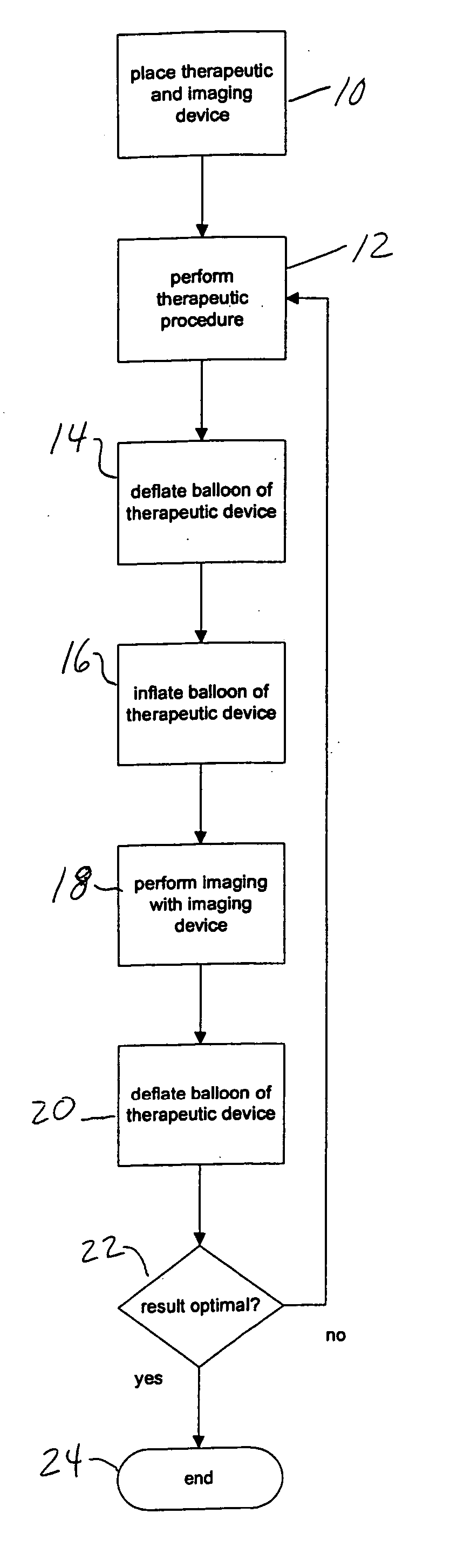
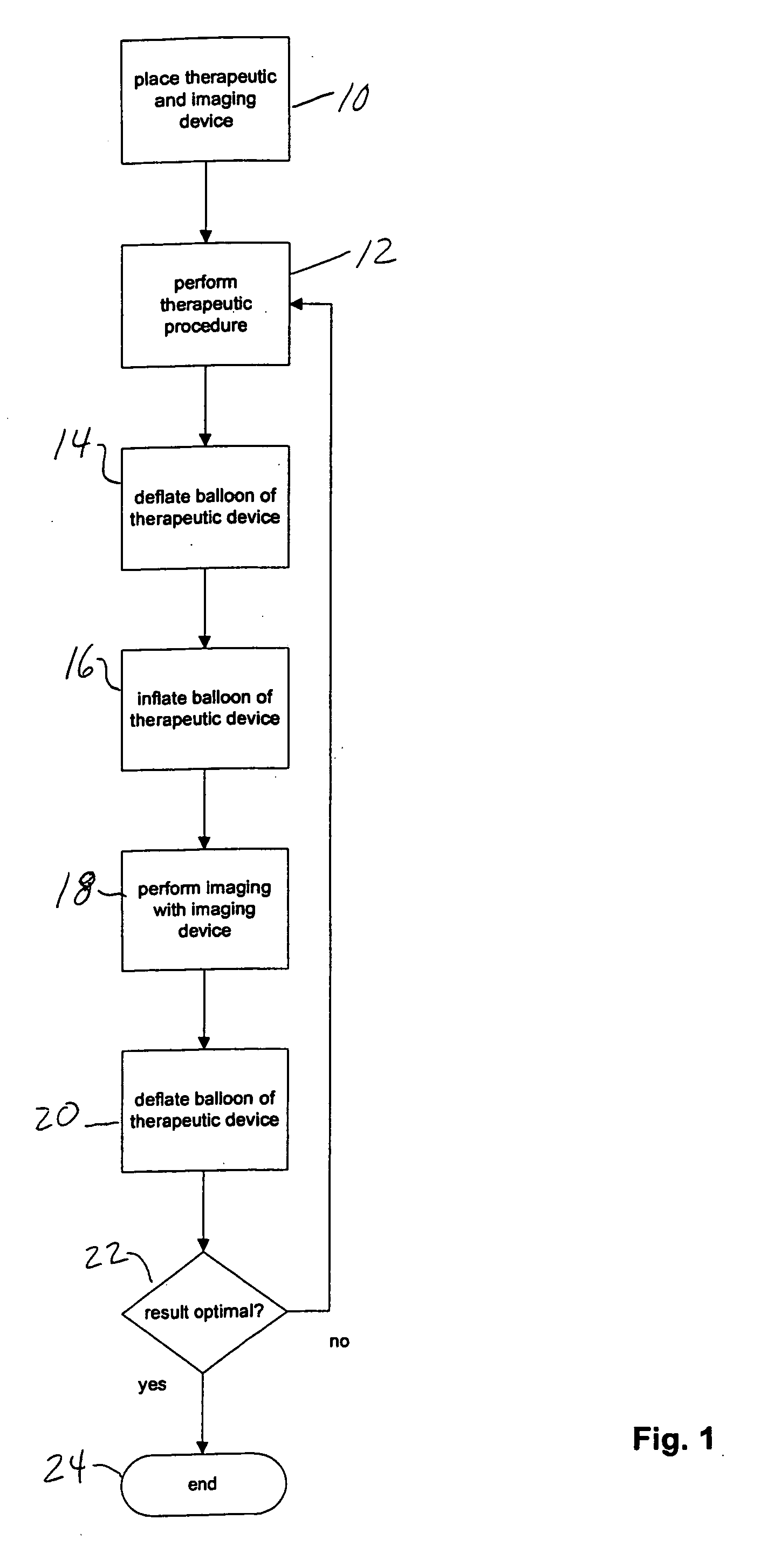
[0026] The present method provides a preferred workflow for online monitoring the therapy control. In a preferred embodiment, the therapeutic procedure for interventional cardiology includes the following consecutive steps.

[0027] 1. Placement, or positioning, of a combined therapeutic device which offers the possibility to monitor the therapeutic procedure under angiographic view. In FIG. 1, this is shown as step 10. The therapeutic device is generally positioned in the afflicted artery. The device of one embodiment is a PTCA (percutaneous transluminal coronary angioplasty) balloon catheter or a stent delivery catheter in combination with an OCT (optical coherence tomography) catheter. Other embodiments of the invention include, but are not limited to, the therapeutic device being one of the devices on the following list: PTA balloon catheter, a bare metal stent, a drug eluting stent, a bioresorbable stent, or a drug eluting bioresorbable stent. Other devices are possible in the pr...


PUM


Abstract

A method is provided for a workflow for cardiovascular intervention that provides online monitoring and therapy control of the procedure. A series of steps are provided utilizing an imaging technology in combination with a therapeutic device to optimize the reliability of the treatment and minimize the negative effects on the patient. In generally, the method steps include: positioning the therapeutic device, performing the therapeutic procedure while imaging the therapeutic device, providing a low pressure inflation of the therapeutic device, imaging the results of the therapeutic procedure, and assessing the result of the therapeutic procedure. If the assessment reveals that the therapeutic procedure result is not optimal, the therapeutic procedure is performed again and the steps thereafter are performed again.

Description

BACKGROUND OF THE INVENTION [0001] 1. Field of the Invention [0002] The present invention relates generally to a method for performing a cardiovascular intervention. [0003] 2. Description of the Related Art [0004] Atherosclerotic vascular disease, the underlying pathology for ischemic heart disease, peripheral arterial occlusive disease and stroke, is the leading cause of death and disability in the modern industrialized countries. Today, after diagnosis of an occlusive disease in the coronaries / peripheral arteries, the main therapeutic approaches are PTCA / PTA (percutaneous transluminal (coronary) angioplasty) and / or stenting of the diseased vessel. Stenting may also be a future option for the treatment of so called “vulnerable” plaques. [0005] Based on angiographic assessment, the degree of the disease, vessel dimensions and the therapeutic approach will be selected. In more complex cases intravascular ultrasound (IVUS) is used to get more detailed information from the diseased ves...

Claims


Application Information

Patent Timeline
Patent Type & Authority Applications(United States)
IPC IPC(8): A61F2/06
CPCA61B5/0066A61B5/0084A61M25/10A61F2/958A61B8/12
Inventor MEISSNER, OLIVERRIEBER, JOHANNESREDEL, THOMAS
Owner SIEMENS AG
Why Eureka
Try Eureka