
Method and device for latency adjustment

a technology of latency adjustment and method, applied in the field of data communication devices, can solve the problems of not offering a way to change the signal latency, reducing the intelligibility of large rooms, and a challenging environment for acoustic communication

Active Publication Date: 2018-09-04
JACOTI
View PDF8 Cites 2 Cited by
  • Summary
  • Abstract
  • Description
  • Claims
  • Application Information

AI Technical Summary

Benefits of technology

The patent describes a method for restoring missing data in a data buffer that includes multimedia data. The method uses a virtual time line representation of the buffer to accurately restore the original data. This helps to maintain the temporal behavior of the data and minimize the negative effects of lost data. Additionally, the patent discusses the use of temporal filtering to adjust the target latency, which can be useful in devices like hearing aids or implantable auditory prosthesis that require low power consumption and low latency. Overall, the patent presents technical methods for enhancing the accuracy and quality of audio data transport in devices with limited resources.

Problems solved by technology

It is well known that large rooms are a challenging environment for acoustic communication.
In addition, the walls of the room add acoustic reverberation to the voice of the teacher, which further reduces its intelligibility.
While the above problems are especially severe for hearing impaired students in a classroom, they are also present outside the classroom, e.g. during a business meeting in a large room, in a room with poor room acoustics or simply because some meeting participants talk or make sounds during a presentation.
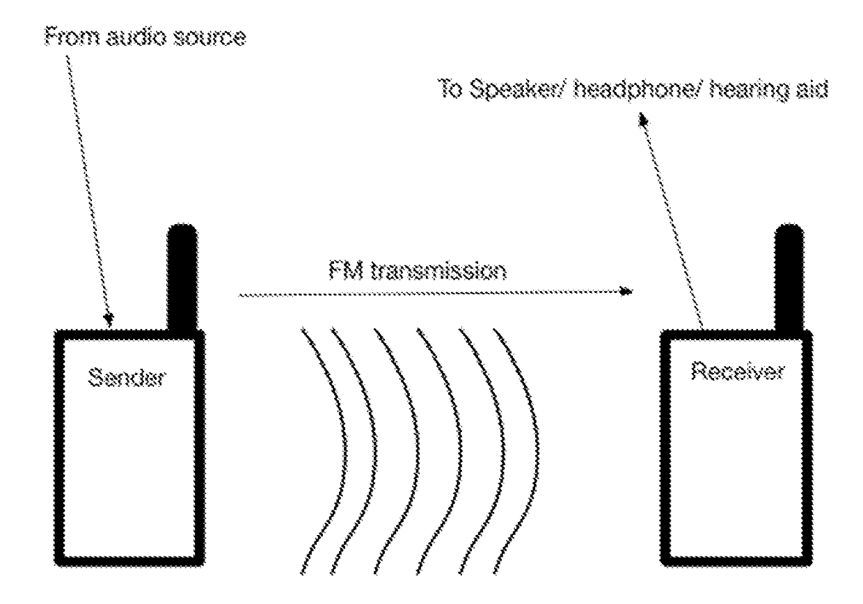
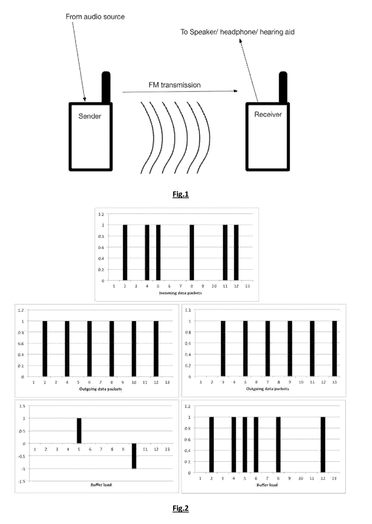
An important limitation of FM systems is that they don't offer a way to change the signal latency.
Another important limitation is that FM systems are analog, offering no way at the end point to perform signal error correction, and they are susceptible to interference.
Those systems are also unidirectional, making it impossible to transmit back audio from the receiver using the same frequency band.
An important challenge in any digital audio solution is to keep the latency introduced by the digital signal processing as low as possible.
To our knowledge, no audio-over-network solution available on the market offers an audio latency over WiFi of less than 100 ms.
Impairments like jitter, radio mode change or other are very detrimental when it comes to a low latency stream of data.
Because of the large latency, these systems are not generally suitable for use to transmit audio on a latency-constrained environment such as for communication in the same room.
It is important to note that in those devices solutions exist that fulfil the above requirements, but to our knowledge, no solution running on those commodity platforms meets the needs of the described latency-constrained environment.

Method used


Image

  • Method and device for latency adjustment
  • Method and device for latency adjustment
  • Method and device for latency adjustment

Examples


Embodiment Construction

[0053]The present invention will be described with respect to particular embodiments and with reference to certain drawings but the invention is not limited thereto but only by the claims.

[0054]Furthermore, the terms first, second and the like in the description and in the claims, are used for distinguishing between similar elements and not necessarily for describing a sequence, either temporally, spatially, in ranking or in any other manner. It is to be understood that the terms so used are interchangeable under appropriate circumstances and that the embodiments of the invention described herein are capable of operation in other sequences than described or illustrated herein.

[0055]It is to be noticed that the term “comprising”, used in the claims, should not be interpreted as being restricted to the means listed thereafter; it does not exclude other elements or steps. It is thus to be interpreted as specifying the presence of the stated features, integers, steps or components as re...


PUM


Abstract

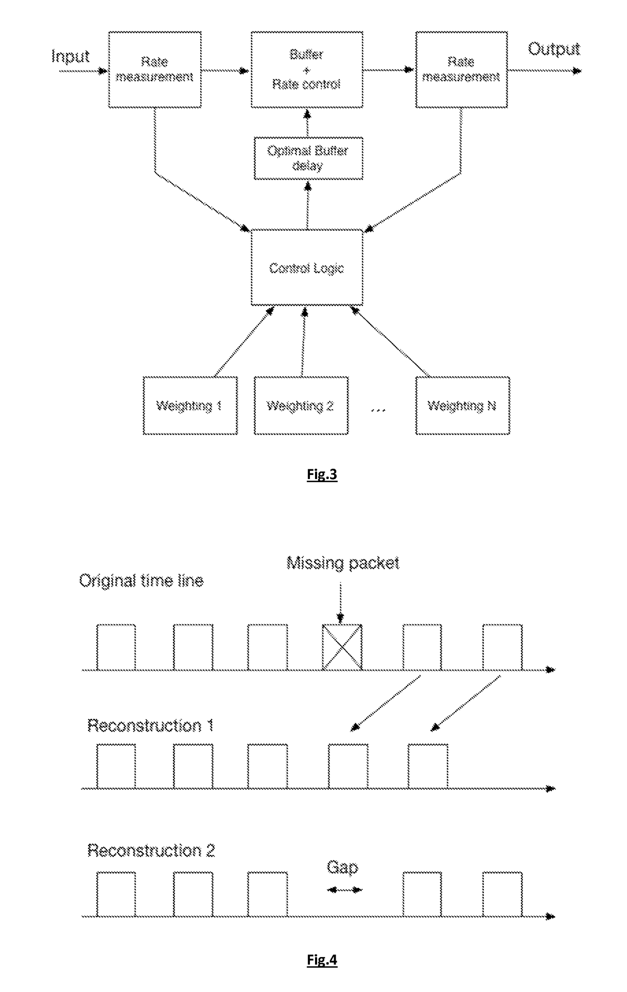
A method for outputting from a device having data communication capability received multimedia data with an adjustable latency comprises the steps of: receiving data packets including the multimedia data and storing the multimedia data in a buffer; measuring at least one characteristic indicative of the input rate of the received data packets; measuring a latency introduced by the buffer; obtaining information indicative of the output rate of the device and determining a target latency for the multimedia data to be outputted based on statistical information derived from the measured at least one characteristic indicative of the input rate and the obtained information indicative of the output rate; adjusting the latency so that it complies with the target latency by modifying the rate at which the multimedia data is outputted or the rate at which the multimedia data is stored in the buffer.

Description

FIELD OF THE INVENTION[0001]The present invention is generally related to the field of devices capable of data communication. More in particular, it relates to the field of solutions for dealing with latency in such devices, i.e. with the time interval between the arrival of a stimulus signal in the device and the outputting of a response signal to that stimulus signal.BACKGROUND OF THE INVENTION[0002]It is well known that large rooms are a challenging environment for acoustic communication. For example, in a typical classroom the distance between the teacher and the students is considerably larger than the typical distance of about 1 to 1.5 meter during a normal one-to-one communication. Therefore, the voice of the teacher is relatively weak at the position of the student. External noise sources as well as the voices or other sounds coming from fellow students add to the acoustics, resulting in a low or even negative signal-to-noise ratio. In addition, the walls of the room add aco...

Claims


Application Information

Patent Timeline
Patent Type & Authority Patents(United States)
IPC IPC(8): H04L12/805H04L12/20H04L21/04H04L29/06H04L12/26H04L12/825G10L21/04H04L47/36
CPCH04L47/25H04L43/0852H04L65/403H04L65/605H04L65/80H04L65/4084G10L21/04H04L65/612H04L65/765
Inventor MENDEZ, NUNKINSBERGEN, JACQUESWACK, NICOLASNEUMANN, JOACHIM
Owner JACOTI
Learn More