Zoom lens system, imaging device and camera

a zoom lens and imaging device technology, applied in the field of zoom lens systems, can solve problems such as not meeting a requested level, and achieve the effects of high zooming ratio, wide view angle and small siz

Inactive Publication Date: 2010-07-08
PANASONIC CORP
View PDF11 Cites 7 Cited by
  • Summary
  • Abstract
  • Description
  • Claims
  • Application Information

AI Technical Summary

Benefits of technology

[0014]An object of the present invention is to provide: a high-performance zoom lens system having a small size and still having a wide view angle at a wide-angle limit as well as a high zooming ratio; an imaging device employing this zoom lens system; and a compact and thin camera employing this imaging device.

Problems solved by technology

Nevertheless, each zoom lens has an insufficient view angle at a wide-angle limit, and hence does not satisfy a requested level in recent years.

Method used


Image

  • Zoom lens system, imaging device and camera
  • Zoom lens system, imaging device and camera
  • Zoom lens system, imaging device and camera

Examples


embodiments i-1 to i-8

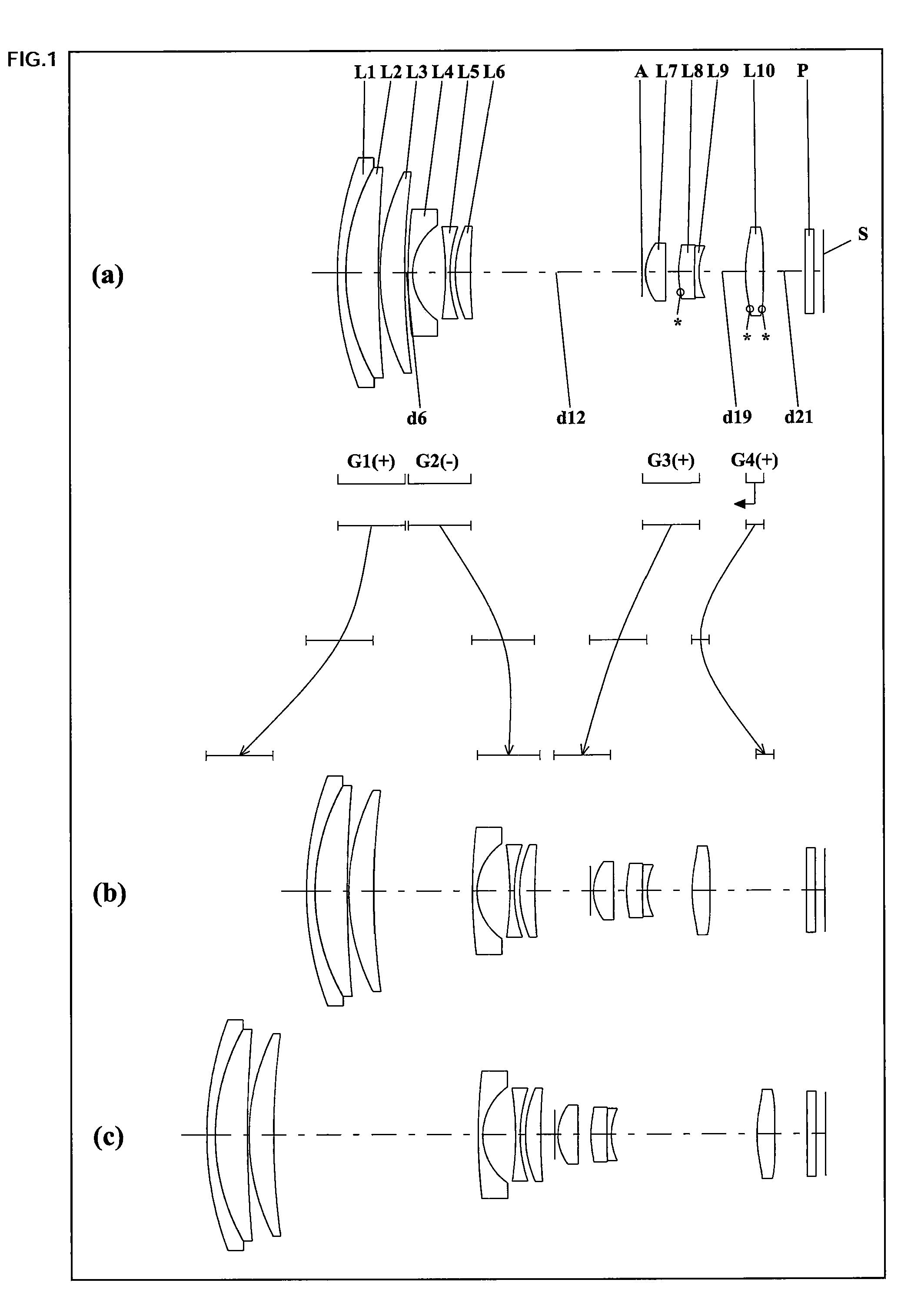
[0219]FIGS. 1, 4, 7, 10, 13, 16, 18 and 21 are lens arrangement diagrams of zoom lens systems according to Embodiments I-1 to 1-8, respectively.

[0220]Each of FIGS. 1, 4, 7, 10, 13, 16, 18 and 21 shows a zoom lens system in an infinity in-focus condition. In each Fig., part (a) shows a lens configuration at a wide-angle limit (in the minimum focal length condition: focal length fW), part (b) shows a lens configuration at a middle position (in an intermediate focal length condition: focal length fM=√{square root over ( )}(fW*fT)), and part (c) shows a lens configuration at a telephoto limit (in the maximum focal length condition: focal length fT). Further, in each Fig., an arrow of straight or curved line provided between part (a) and part (b) indicates the movement of each lens unit from a wide-angle limit through a middle position to a telephoto limit. Moreover, in each Fig., an arrow imparted to a lens unit indicates focusing from an infinity in-focus condition to a close-object in...

embodiments ii-1 to ii-9

[0281]FIGS. 25, 28, 31, 33, 35, 38, 41, 44 and 47 are lens arrangement diagrams of zoom lens systems according to Embodiments II-1 to II-9, respectively.

[0282]Each of FIGS. 25, 28, 31, 33, 35, 38, 41, 44 and 47 shows a zoom lens system in an infinity in-focus condition. In each Fig., part (a) shows a lens configuration at a wide-angle limit (in the minimum focal length condition: focal length fW), part (b) shows a lens configuration at a middle position (in an intermediate focal length condition: focal length fM=√{square root over ( )}(fW*fT)), and part (c) shows a lens configuration at a telephoto limit (in the maximum focal length condition: focal length fT). Further, in each Fig., an arrow of straight or curved line provided between part (a) and part (b) indicates the movement of each lens unit from a wide-angle limit through a middle position to a telephoto limit. Moreover, in each Fig., an arrow imparted to a lens unit indicates focusing from an infinity in-focus condition to a...

embodiments iii-1 to iii-7

[0349]FIGS. 51, 54, 57, 59, 61, 64 and 67 are lens arrangement diagrams of zoom lens systems according to Embodiments III-1 to III-7, respectively.

[0350]Each of FIGS. 51, 54, 57, 59, 61, 64 and 67 shows a zoom lens system in an infinity in-focus condition. In each Fig., part (a) shows a lens configuration at a wide-angle limit (in the minimum focal length condition: focal length fW), part (b) shows a lens configuration at a middle position (in an intermediate focal length condition: focal length fM=√{square root over ( )}(fW*fT)), and part (c) shows a lens configuration at a telephoto limit (in the maximum focal length condition: focal length fT). Further, in each Fig., an arrow of straight or curved line provided between part (a) and part (b) indicates the movement of each lens unit from a wide-angle limit through a middle position to a telephoto limit. Moreover, in each Fig., an arrow imparted to a lens unit indicates focusing from an infinity in-focus condition to a close-object ...


PUM


Abstract

A zoom lens system, in order from an object side to an image side, comprising a first lens unit of positive power, a second lens unit of negative power, a third lens unit of positive power, and a fourth lens unit of positive power, wherein the first lens unit is composed of three or fewer lens elements, wherein the second lens unit is composed of three lens elements, wherein in zooming, the first to the fourth lens units are moved individually along an optical axis such that air spaces should vary, so that variable magnification is achieved, and wherein the conditions are satisfied: tan 2ωW×m2W≦−1.78, tan 2ωW×|fG2|/fG1≧1.24, ωW≧37 and fT/fW≧10 (m2W is a lateral magnification of the second lens unit at a wide-angle limit, fG1 and fG2 are composite focal lengths of the first and the second lens units, ωW is a half view angle at a wide-angle limit, and fT and fW are focal lengths of the entire system respectively at a telephoto limit and at a wide-angle limit), an imaging device and a camera are provided.

Description

CROSS-REFERENCE TO RELATED APPLICATION[0001]This application is based on application Nos. 2009-002554, 2009-002555 and 2009-002556 filed in Japan on Jan. 8, 2009, the contents of which are hereby incorporated by reference.BACKGROUND OF THE INVENTION[0002]1. Field of the Invention[0003]The present invention relates to a zoom lens system, an imaging device and a camera. In particular, the present invention relates to: a high-performance zoom lens system having a small size and still having a wide view angle at a wide-angle limit as well as a high zooming ratio; an imaging device employing this zoom lens system; and a compact and thin camera employing this imaging device.[0004]2. Description of the Background Art[0005]Remarkably strong requirements of size reduction and performance improvement are present in digital still cameras and digital video cameras (simply referred to as digital cameras, hereinafter) provided with an image sensor for performing photoelectric conversion. In parti...

Claims


Application Information

Patent Timeline
Patent Type & Authority Applications(United States)
IPC IPC(8): H04N5/262G02B15/14
CPCG02B15/173G02B15/144113
Inventor TOHCHI, YASUNORIKURIOKA, YOSHIAKIBITO, TAKAKAZU
Owner PANASONIC CORP
Why Eureka
Try Eureka