
Lens activating device

a technology of activating device and lens, which is applied in the direction of dynamo-electric components, dynamo-electric machines, metabolism disorders, etc., can solve the problems of inevitably increasing production costs, more difficult to develop press-forming molds for supporting arms, and damage to elastic pieces, so as to reduce the rotation of a movable piece of the lens activating device.

Inactive Publication Date: 2010-07-08
WAH HONG INDAL CORP
View PDF7 Cites 10 Cited by
  • Summary
  • Abstract
  • Description
  • Claims
  • Application Information

AI Technical Summary

Benefits of technology

[0015]The objective of the present invention is to provide a lens activating device, whereby the slight rotation of a movable piece of the lens activating device can be reduced. Further, the problem that the elastic piece may scrape neighboring elements can be prevented.
[0016]Another objective of the present invention is to provide a lens activating device, in which the elastic piece is integrally formed so as to simplify the whole structure. Via this arrangement, the difficulty in designing the press-forming mold is reduced. As a result, the production cost is reduced and the yield of products can be improved.
[0019]The present invention has advantageous features as follows. By using the elastic piece of a closed ring structure, the slight rotation of the movable piece in the lens activating device can be reduced. Further, the problem that the elastic piece may scrape the neighboring elements can be prevented.

Problems solved by technology

As a result, the elastic piece may suffer damage and even get failure.
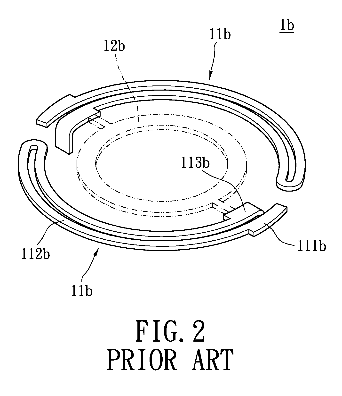
If the construction of the elastic piece is more complicated, such as that in JP 2006-201525, in which the supporting arm is formed with continuous bends, it is more difficult to develop the press-forming molds for the supporting arm.
As a result, the production cost may be inevitably increased and the yield of products may be deteriorated.
Thus, the production cost and working hours are increased undesirably.
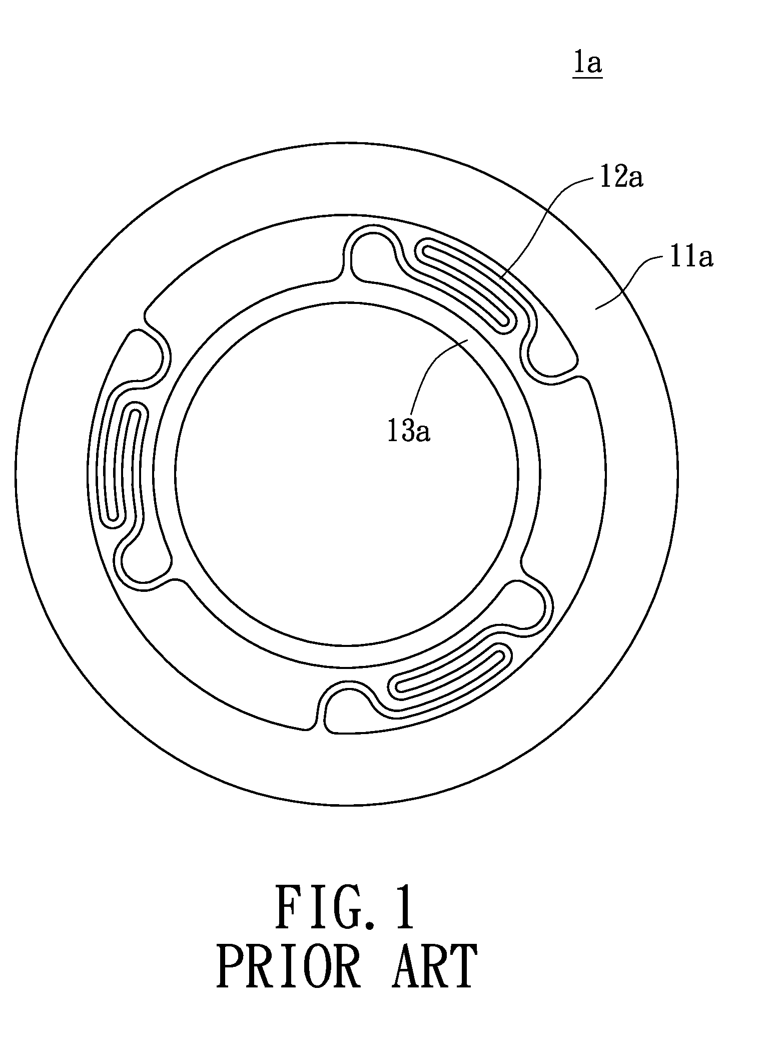
In addition, it is more important to appreciate that a wrist 913a of the upper elastic piece 91a is connected to the inner ring 911a and the outer ring 912a, and it is used as a flexible section when the outer ring 911a moves with respect to the inner ring 912a. However, such a wrist 913a is formed with continuous bends, so that it cannot be manufactured easily and may suffer damage.

Method used


Image

  • Lens activating device
  • Lens activating device
  • Lens activating device

Examples


Embodiment Construction

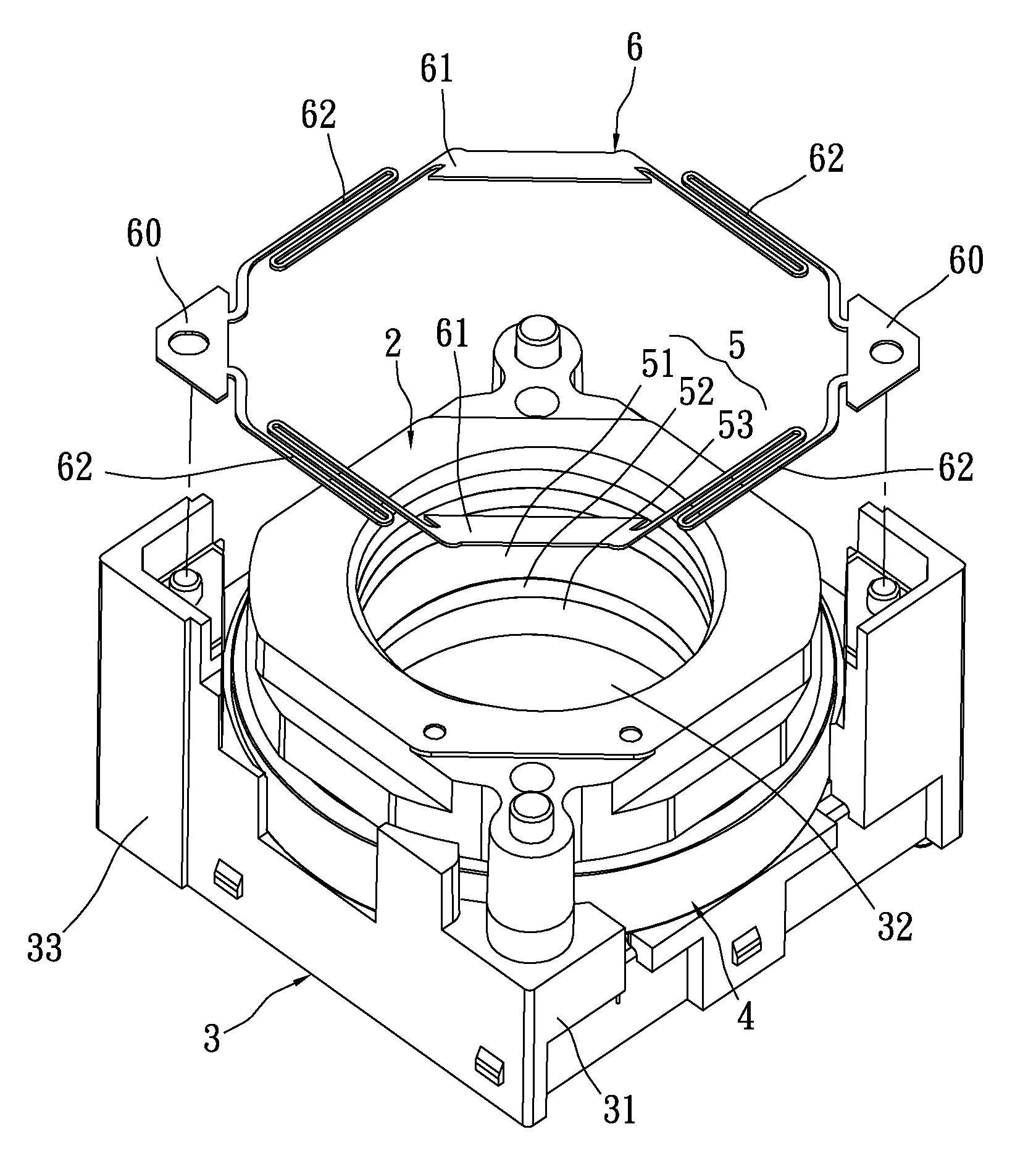
[0029]Please refer to FIGS. 5 to 7, which show the first embodiment of the present invention. The present invention provides a lens activating device, which includes a lens assembly 2, a fixing seat 3, a coil assembly 4, at least one magnetic element 5 and at least one elastic piece 6.

[0030]The lens assembly 2 has an imaging lens (not shown). After the lens assembly 2 and the magnetic element 5 are assembled together, a movable piece of the present invention can be formed. The magnetic element 5 comprises a first magnet 51, a ferromagnetic piece 52 and a second magnet 53. The first magnet 51 and the second magnet 53 are combined to both surfaces of the ferromagnetic piece 52 with the same magnetic polarities facing to each other. Via this arrangement, the magnetic element 5 can be formed.

[0031]Furthermore, after the fixing seat 3 and the coil assembly 4 are assembled, a stationary piece of the present invention can be formed. The movable piece is connected into the stationary piece ...


PUM


Abstract

A lens activating device includes at least one elastic piece, at least one stationary piece and a movable piece. At least one elastic piece has at least four sheet portions and four sets of elastic portions. Each set of the elastic portions are serpentine and connected between two sheet portions in order to make the at least one elastic piece form a closed ring. The stationary piece is connected to two sheet portions, and the movable portion is connected to the other two sheet portions. The elastic force generated by the four sets of elastic portions exerts a restoring force on the movable piece. Via this arrangement, the slight rotation of the movable piece within the lens activating device can be reduced. Further, the problem that the elastic piece may scrape the neighboring elements can be prevented.

Description

BACKGROUND OF THE INVENTION[0001]1. Field of the Invention[0002]The present invention relates to a lens activating device, and in particular, to a lens activating device for driving lens of a micro imaging module.[0003]2. Description of Related Art[0004]Recently, it becomes more and more popular for portable devices such as mobile phones or PDA to be equipped with an imaging module. Furthermore, since the market requires these portable devices to have more powerful functions and smaller sizes, it is necessary for the imaging module to generate high quality pictures and to be of small size accordingly. One improvement of picture quality is to increase the number of pixel. The pixel number of an imaging module has already increased from the VGA-level 30 pixels to 2, 3 or even 8 million pixels, which is now common in the market. Another improvement lies in the definition of the image. Thus, the imaging module of a portable device also develops from a fixed-focus mode to auto-focus mode...

Claims


Application Information

Patent Timeline
Patent Type & Authority Applications(United States)
IPC IPC(8): G02B7/04G02B7/02
CPCG02B7/08H02K41/0356A61P1/00A61P3/04A61P9/10
Inventor LAI, MEI-LINGKUO, LI-TE
Owner WAH HONG INDAL CORP
Learn More