Forming Apparatus

a technology of forming apparatus and material, applied in the field of materials, can solve problems such as the possibility of undesired gaps and variations in orientation, inferior production, and excessive stress and pressure in the system

Active Publication Date: 2010-07-08
MFG SYST LTD
View PDF18 Cites 25 Cited by
  • Summary
  • Abstract
  • Description
  • Claims
  • Application Information

AI Technical Summary

Benefits of technology

[0104]Optionally, but preferably for thermoforming, the guide(s) over the pressure forming zone provide a pinching effect as the dies progress into and / or through the pressure zone.
[0162]Degrees of freedom between the surface tool and its carrier tool are provided by keying which allows such relative expansion of the two.

Problems solved by technology

A difficulty with forming of different kinds (whether under pressure alone such as drawing (deep or shallow) and imprinting, or pressure and temperature such as injection moulding, blow moulding, extrusion, vacuum forming, thermoforming, pressure forming, compression moulding (e.g. for rubber or cross-linkable materials) vacuum forming in conjunction with material extrusion, thermoforming in conjunction with extrusion and / or vacuum forming, calendaring and post processing and similar forming processes) is the need to ensure an ability for the apparatus
A difficulty, for example, in mating or co-acting dies or other forming tools (“forming tools”) is the prospect of undesired gaps and variations in orientation over the forming zone (hereafter “pressure forming zone”).
This is irrespective of whether or not the forming tools simply receive material under pressure (e.g. injection moulding) or apply pressure to a material not being introduced under pressure (e.g. extrusion and then thermoforming), or some hybrid thereof, as there is the prospect of material being entrapped between adjacent forming tools and thereby giving rise to inferior production and excessive stresses and pressure(s) in the system.
The presence of such a nip point creates, as can be appreciated, problems and join lines in the finished product.

Method used


Image

  • Forming Apparatus
  • Forming Apparatus
  • Forming Apparatus

Examples


Embodiment Construction

[0261]As used herein the term “and / or” means “and” or “or”, or both.

[0262]As used herein the term “(s)” following a noun includes, as might be appropriate, the singular or plural forms of that noun.

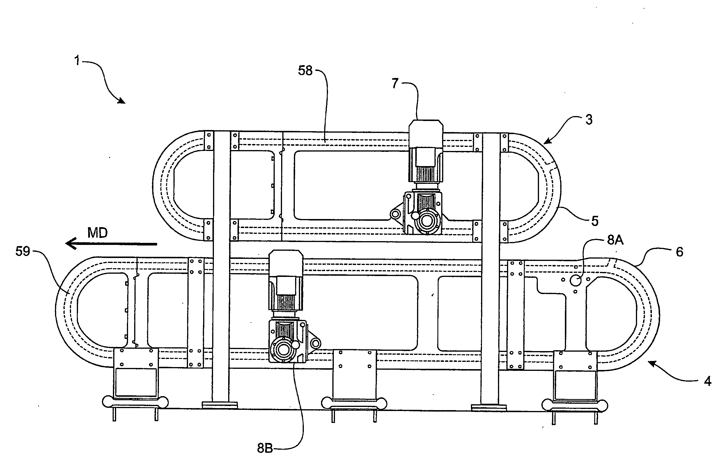
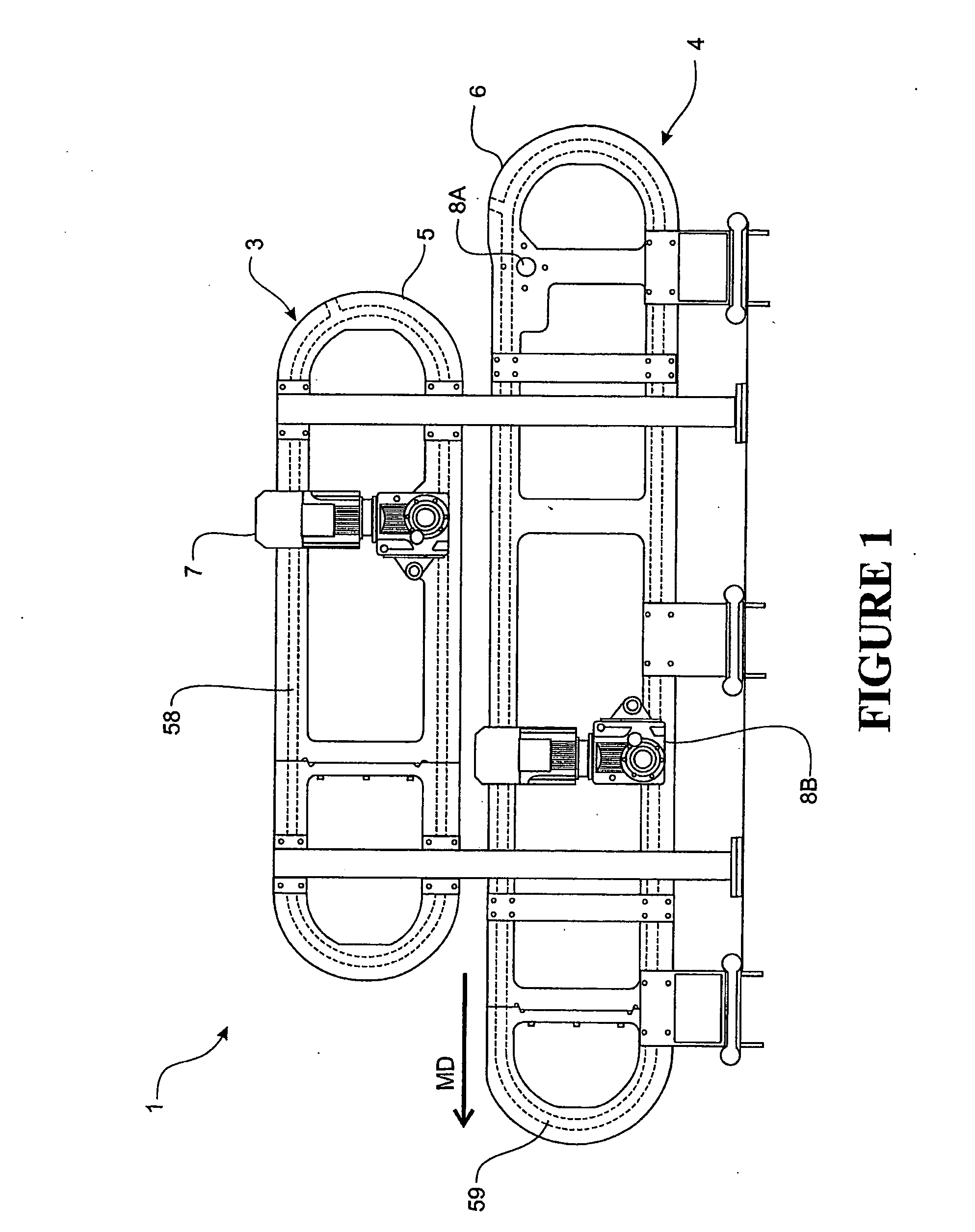
[0263]We recognise an advantage in providing forming apparatus (1) of a kind that moves two sets of tooling parts (forming tools (11) in procession continuously or continually when in use (regardless of continuous or stop start motion, hereinafter referred to as a “continuous” process) to bring a forming tool (11) into a co-acting condition with a complementary forming tool (11) to then pressurise or hold the co-acting forming tools against pressure to the tolerances required for the material or materials to be formed, and then to separate the forming tools. Such a process may be at a controlled temperature also.

[0264]The forming apparatus (1) generally consists of a first forming tool set (or upper die set) (3) carrying, defining and / or forming an upper forming surface (23), and a second...


PUM

PropertyMeasurementUnit
clamping pressuresaaaaaaaaaa
pressureaaaaaaaaaa
velocityaaaaaaaaaa

Abstract

The present invention relates to a forming apparatus for forming a formable material or materials. The apparatus has a first forming tool set, and a second forming tool set. Each forming tool of the second forming tool set is adapted to co-act with one or more forming tools of the first forming tool set, or vice versa, to form a co-acting forming tool in a pressure forming zone. There is a first forming tool set guide or guides about which the first forming tool set can be moved about a first circuit. There is also a second forming tool set guide or guides about which the second forming tool set can be moved about a second circuit. There is also a drive means to drive the tools in a machine direction. At least on part of the circuit, immediately before or after the pressure forming zone, adjacent forming tools of one the forming tool sets are movably supported such that the only relative movement of said adjacent forming tools is towards or away from the forming tools of the other forming tool set with which they co-act.

Description

FIELD OF INVENTION[0001]This invention relates to forming apparatus for materials.BACKGROUND OF THE INVENTION[0002]A difficulty with forming of different kinds (whether under pressure alone such as drawing (deep or shallow) and imprinting, or pressure and temperature such as injection moulding, blow moulding, extrusion, vacuum forming, thermoforming, pressure forming, compression moulding (e.g. for rubber or cross-linkable materials) vacuum forming in conjunction with material extrusion, thermoforming in conjunction with extrusion and / or vacuum forming, calendaring and post processing and similar forming processes) is the need to ensure an ability for the apparatus[0003](i) to meet tolerances required,[0004](ii) to be brought to its operating conditions without fouling,[0005](iii) to be operated whether at operating temperature(s) or not without destructive interferences, and[0006](iv) to be brought to the forming zone (preferably a pressure zone) with or without any tracked or guid...

Claims


Application Information

Patent Timeline
Patent Type & Authority Applications(United States)
IPC IPC(8): B29C45/12B29C48/12
CPCB29C43/00B29C43/06B29C47/003B30B11/14B29C47/0054B29C2043/3283B29C2043/5833B29C47/004B29C43/48B29C2043/483B29C48/0011B29C48/12B29C48/0017B29C2049/4862B29C39/06A21C15/00A21C9/08B28B5/02
Inventor HAYNES, ANDREW LEONICHOLLS, CHRISTOPHER JOHNGIURGIU, GABRIEL JOANBUCKINGHAM, SAMUEL GWYNN
Owner MFG SYST LTD
Why Eureka
Try Eureka