Magnetically guided catheter

Active Publication Date: 2010-07-08
ST JUDE MEDICAL ATRIAL FIBRILLATION DIV
View PDF119 Cites 91 Cited by
  • Summary
  • Abstract
  • Description
  • Claims
  • Application Information

AI Technical Summary

Benefits of technology

[0008]In various embodiments, magnetic guided catheters are disclosed that are manufacturable at relativ

Problems solved by technology

Such catheter devices can be complex in their construction, and therefore are difficult to manufacture and relatively expensive to produce.
T

Method used


Image

  • Magnetically guided catheter
  • Magnetically guided catheter
  • Magnetically guided catheter

Examples


Example

[0032]Many specific details of certain embodiments of the invention are set forth in the following description in order to provide a thorough understanding of such embodiments. One skilled in the art, however, will understand that the present invention may have additional embodiments, or that the present invention may be practiced without several of the details described in the following description.

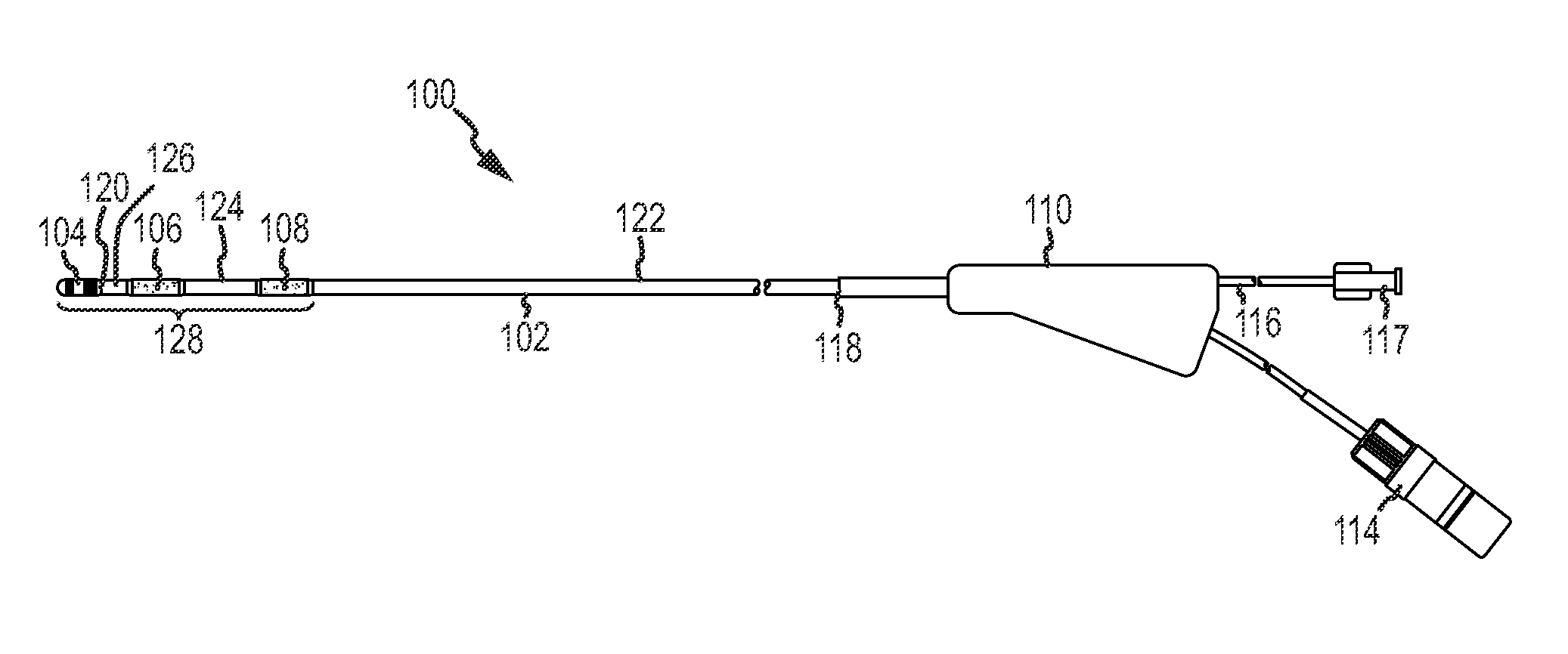
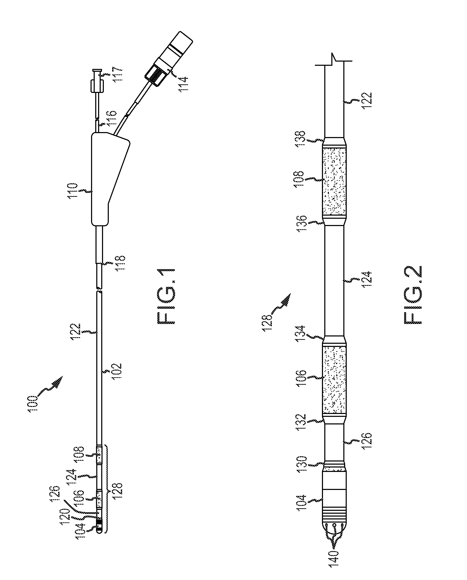
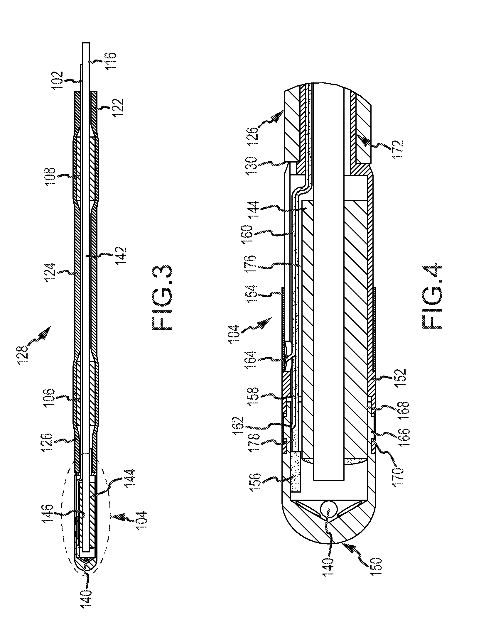
[0033]FIG. 1 illustrates a first exemplary non-steerable, single-use magnetically guided catheter 100 generally including a flexible outer tube, or tubing, 102, a tip assembly 104, positioning magnets 106 and 108 separately provided from and spaced from tip assembly 104, a Y connector 110, a luer device 112, and an electrical connector 114. Luer device 112 is used to open or close a flow path so that fluid is passed through Y-connector 110 and tubing 102 to tip assembly 104 for irrigation purposes. Electrical connector 114 establishes electrical connection with a power source (not shown)...


PUM


Abstract

A catheter comprising a flexible tubing having a proximal end and a distal end. An electrode assembly is attached to the distal end of the flexible tubing. The electrode assembly includes an electrically conductive tip electrode and a coupler which is connected between the tip electrode and the distal end of the flexible tubing. The coupler and the tip electrode are coupled by an interlocking connection. A first magnet is at least partially housed in the coupler. A fluid lumen extends through the flexible tubing to the coupler. The fluid lumen extends completely through the first magnet and connects to at least one port formed in the electrode assembly. A second magnet is spaced from the electrode assembly along a longitudinal axis of the tubing. The first magnet and the second magnet are responsive to an external magnetic field to selectively position and guide the electrode assembly within a body of a patient.

Description

CROSS-REFERENCE TO RELATED APPLICATIONS[0001]This application claims priority to and the benefit of U.S. Provisional Application No. 60 / 947,791, filed 3 Jul. 2007 (the '791 application), and international patent application numbers PCT / US2008 / 069,241 (the '241 application) PCT / 2008 / 069,248 (the '248 application) both of which were filed 3 Jul. 2008. This application is also a continuation-in-part of U.S. non-provisional application Ser. Nos. 12 / 667,338 filed 30 Dec. 2009 (the '338 application) and 12 / 167,736, filed 3 Jul. 2008 (the '736 application), which in turn claims the benefit of the '791 application and the '241 application. The entire contents of each of the '791, the '241, the '248, the '338, and the '736 applications are hereby incorporated by reference as though fully set forth herein.BACKGROUND OF THE INVENTION[0002]a. Field of the Invention[0003]This invention relates generally to medical instruments, and, more specifically, to a navigable catheter device positionable w...

Claims


Application Information

Patent Timeline
IPC IPC(8): A61B5/05A61M25/00
CPCA61B5/06A61B18/1492A61B2018/00577A61B2018/00821A61M2025/0166A61M25/0012A61M25/005A61M25/0127A61B2218/002A61B5/062
Inventor WU, KIRK
Owner ST JUDE MEDICAL ATRIAL FIBRILLATION DIV
Why Eureka
Try Eureka