Extended range of motion, constrained prosthetic hip-joint

a prosthetic hip and joint technology, applied in the field of prosthetic acetabulum cup and liner assembly, can solve the problems of dislocation of the femoral head from the acetabulum or the hip socket, high stress and high sheer load applied to the femoral neck, and the inability to provide a hip replacement that matches the original healthy hip joint, etc., to achieve the effect of reducing the time interval required, improving rehabilitation, and reducing the time interval

Inactive Publication Date: 2010-07-08
LEWIS RALPH H
View PDF2 Cites 37 Cited by
  • Summary
  • Abstract
  • Description
  • Claims
  • Application Information

AI Technical Summary

Benefits of technology

[0027]Yet another object of the present disclosure is to provide an improved prosthetic hip-joint which improves rehabilitation from an implantation procedure.
[0028]Yet another object of the present disclosure is to provide an improved prosthetic hip-joint which reduc...

Problems solved by technology

However, as described below it appears that there still exist obstacles to providing a prosthetic hip replacement that matches the original healthy hip joint.
This angular transmission of the load and forces through the femoral neck results in high stresses and high sheer-loads applied to the femoral neck.
These high stresses, when normally applied can cause dislocation of the femoral head from the acetabulum or hip socket, and fracture or breaking of the femoral neck.
In older people the femoral neck often becomes brittle, and in both older and younger people is subject to fracture.
When the ligaments of the natural joint are resected during the reconstructive procedure, the artificial joint is inherently less stable and subject to dislocation.
Consequently, there exists an increased potential for artificial joint dislocation when ...

Method used


Image

  • Extended range of motion, constrained prosthetic hip-joint
  • Extended range of motion, constrained prosthetic hip-joint
  • Extended range of motion, constrained prosthetic hip-joint

Examples


Embodiment Construction

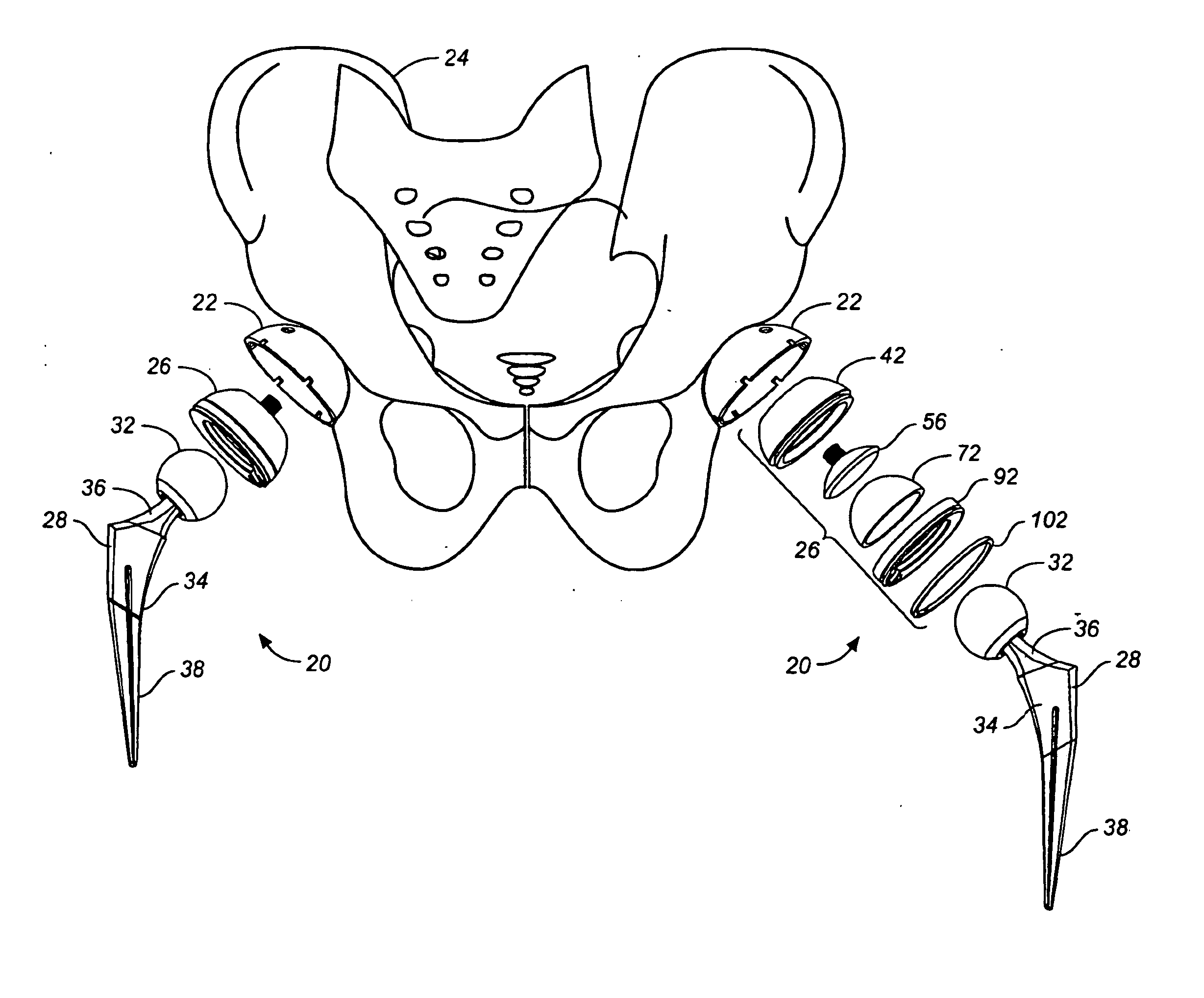
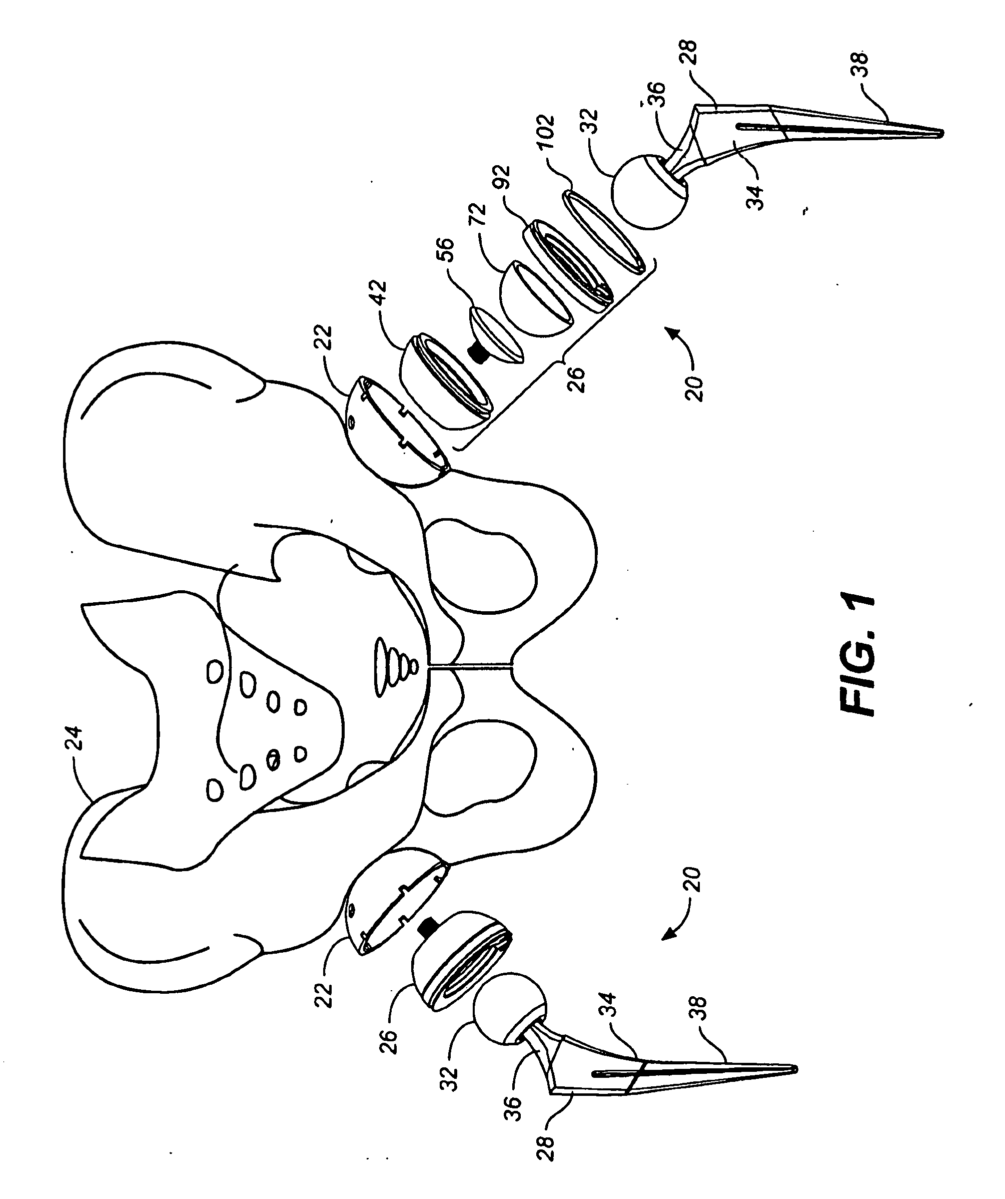
[0047]The perspective diagram of FIG. 1 depicts an identical pair of extended range of motion, constrained prosthetic hip-joints in accordance with the present disclosure referred to by the general reference character 20. The prosthetic hip-joint 20 appearing on the left hand side of FIG. 1 illustrates major subassemblies making up the prosthetic hip-joint 20 which include a prosthetic acetabulum cup 22 that is adapted for implantation into a pelvis bone 24. The prosthetic hip-joint 20 also includes a liner assembly 26, described in greater detail below, which during implantation of the prosthetic hip-joint 20 is fixed to the acetabulum cup 22.

[0048]The prosthetic hip-joint 20 further includes a prosthetic femoral assembly 28. The femoral assembly 28 includes a prosthetic, ball-shaped femoral head 32 and a prosthetic femoral stem 34. A first end 36 of the femoral stem 34 is fixed to the femoral head 32 while a second end 38 of the femoral stem 34 distal from the first end 36 is adap...


PUM

PropertyMeasurementUnit
Angleaaaaaaaaaa
Angleaaaaaaaaaa
Angleaaaaaaaaaa

Abstract

A prosthetic hip-joint includes: a. a prosthetic acetabulum cup for implantation into a pelvis; b. a prosthetic femoral assembly which includes: i. a ball-shaped femoral head that during implantation becomes located within the cup; and ii. a femoral stem that is fixed at a first end to the head, and that has a second end distal from the first end which is adapted for implant into a medullary canal of a femur, and c. a liner assembly adapted to he secured to the cup and is also adapted to receive and to constrain the head against dislocation. In one aspect the hip-joint permits the head to rotate through an angle which exceeds at least 153 degrees while concurrently constraining the head against dislocation. In another aspect the hip joint constrains the head a dislocation by a preestablished amount of force which is adjustable during implantation thereof.

Description

TECHNICAL FIELD [0001]The present invention relates to implantable prosthetic devices for hip-joint replacement in a human body. More particularly, the present disclosure relates to a prosthetic acetabulum cup and liner assembly as well as a prosthetic ball attached to a prosthetic femur, the acetabulum cup and liner assembly controllably constraining the ball in the acetabulum cup and liner assembly.BACKGROUND ART [0002]During recent years the number of people requiring a joint replacement has been increasing. A paper entitled “Developing PEEK Polymer as a Bearing Material for Implants,” John Devine, ©2006 Medical Devices & Diagnostic Industry, reports that each year approximately 1.4 million joint replacement procedures are performed worldwide. Of joint replacement procedures, a paper entitled “Failure Analysis of Composite Femoral Components for Hip Arthroplasty,” Chaodi Li, PhD; et al., Journal of Rehabilitation Research & Development, Vol. 40, No. 2, March / April 2003, pp. 131-1...

Claims


Application Information

Patent Timeline
IPC IPC(8): A61F2/32
CPCA61F2/30965A61F2/32A61F2002/30495A61F2002/3208A61F2002/325A61F2002/3283A61F2310/00407A61F2002/3408A61F2002/3438A61F2002/3448A61F2220/0025A61F2310/00029A61F2310/00161A61F2002/3404A61F2002/30593A61F2002/3241A61F2002/3403
Inventor LEWIS, RALPH H.
Owner LEWIS RALPH H
Why Eureka
Try Eureka