Heat dissipating structure and method of manufacturing same

a heat dissipating structure and heat dissipating technology, applied in the direction of heat transfer modification, indirect heat exchangers, light and heating apparatus, etc., can solve the problems of bringing hazards to human bodies, environmental pollution, environmental pollution, etc., and achieve good heat conducting and dissipating effects

Inactive Publication Date: 2010-07-15
ASIA VITAL COMPONENTS SHENZHEN CO LTD
View PDF2 Cites 1 Cited by
  • Summary
  • Abstract
  • Description
  • Claims
  • Application Information

AI Technical Summary

Benefits of technology

[0009]A primary object of the present invention is to provide a heat dissipating structure that has a plurality of heat pipes tightly fitted between a base and

Problems solved by technology

The above-described conventional heat dissipating structure 1 has a main problem in implementation thereof.
By doing this, it tends to cause environmental pollution and hazards to human body.
In brie

Method used


Image

  • Heat dissipating structure and method of manufacturing same
  • Heat dissipating structure and method of manufacturing same
  • Heat dissipating structure and method of manufacturing same

Examples


first embodiment

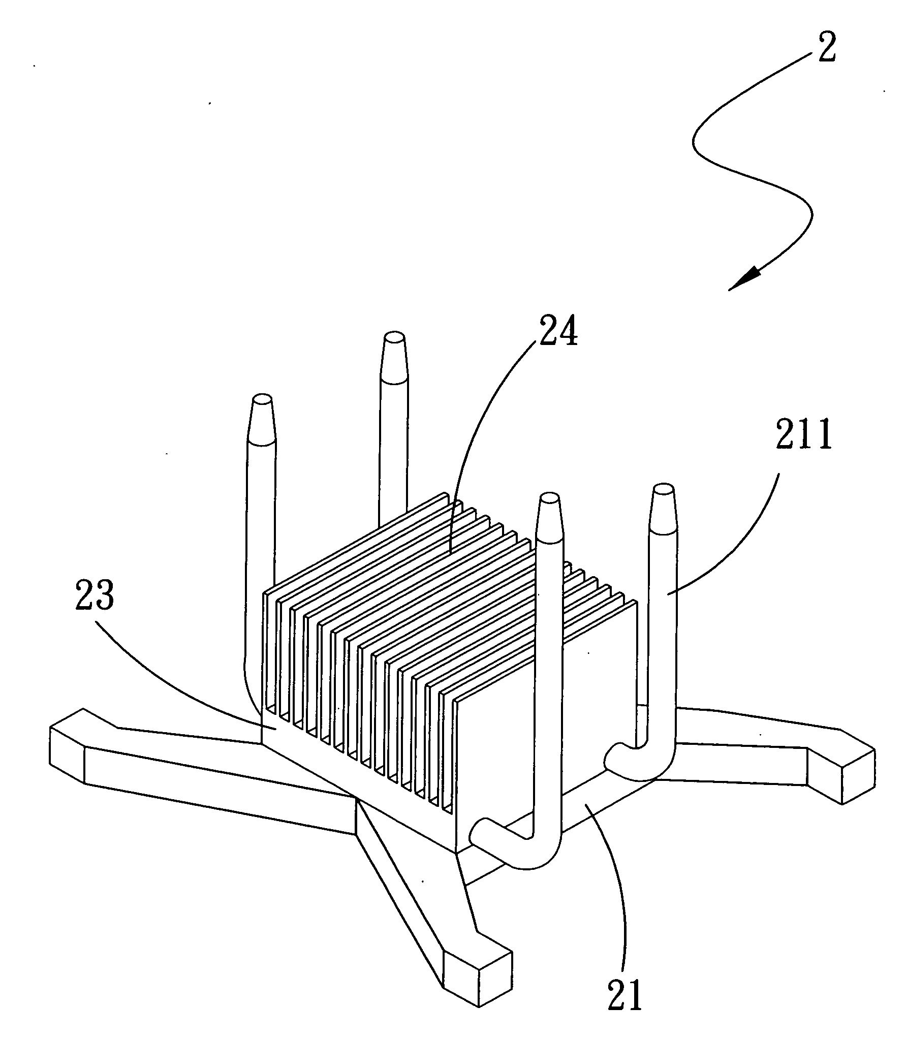
[0024]The present invention also provides a method of manufacturing the heat dissipating structure 2. Please refer to FIG. 7, in the method of manufacturing the heat dissipating structure 2 according to the present invention, the following steps are included:[0025]Step S11: positioning a plurality of heat pipes 22 in lower pipe-receiving grooves 211 formed on a base 21;[0026]Step S12: closing a cover 23 onto the heat pipes 22, so that upper pipe-receiving grooves 231 correspondingly formed on the cover 23 are engaged with the heat pipes 22;[0027]Step S13: applying a heat-conducting substance 3 between the heat pipes 22 and the base 21 and between the heat pipes 22 and the cover 23; and[0028]Step S14: pushing the cover 23 against the base 21 for them to tightly connect to each other and thereby fixedly hold the heat pipes 22 therebetween.

[0029]The heat dissipating structure 2 formed through above-described steps has tightly closed and connected base 21 and cover 23 while the heat pip...

second embodiment

[0030]In the method of manufacturing the heat dissipating structure 2 according to the present invention as shown in FIG. 8, the following steps are included:[0031]Step S21: applying a heat-conducting substance 3 in lower pipe-receiving grooves 211 formed on a base 21;[0032]Step S22: positioning a plurality of heat pipes 22 in the lower pipe-receiving grooves 211 on the base 21;[0033]Step S23: applying a heat-conducting substance 3 in upper pipe-receiving grooves 231 formed on a cover 23;[0034]Step S24: closing the cover 23 onto the heat pipes 22 with the upper pipe-receiving grooves 231 engaging with the heat pipes 22;[0035]Step S25: pushing the cover 23 against the base 21 for them to tightly connect to each other and thereby fixedly hold the heat pipes 22 therebetween.

[0036]In forming the heat dissipating structure 2 through the above-described steps, the heat-conducting substance 3 is first applied in the lower and upper pipe-receiving grooves 211, 231 on the base 21 and the cov...


PUM


Abstract

A heat dissipating structure and a method of manufacturing same is disclosed. The heat dissipating structure includes a base being formed on one face with lower pipe-receiving grooves, a cover being formed on one face facing to the base with upper pipe-receiving grooves, and heat pipes disposed between the base and the cover. A heat-conducting substance is applied in the lower and upper pipe-receiving grooves, whereby when the cover is tightly pushed against the base, the heat pipes are tightly fitted in and between the lower and the upper pipe-receiving grooves. Radiating fins can be provided on the cover. When the base is attached at another face to an electronic device, heat produced by the electronic device can be effectively transferred to and dissipated from the heat dissipating structure, which has tightly connected base, heat pipes, and cover to ensure high heat dissipating effect without the need of tin soldering.

Description

FIELD OF THE INVENTION[0001]The present invention relates to a heat dissipating structure and a method of manufacturing same; and more particularly to a heat dissipating structure and a method of manufacturing same that avoids environmental pollution and hazards to human body caused by tin soldering.BACKGROUND OF THE INVENTION[0002]According to currently available techniques, when using a heat pipe, the heat pipe has one end being located at a high-temperature interface and another end at a low-temperature interface, so that heat transfer in the heat pipe occurs. That is, at the high-temperature interface, heat passes through a metal wall of the heat pipe into a wick structure provided inside the heat pipe. A working fluid in the wick structure is heated and evaporates. The end of the heat pipe at the high-temperature interface is referred to as an evaporating section. The vapor of the evaporated working fluid gathers in a hollow pipe at the evaporation section and flows to the othe...

Claims


Application Information

Patent Timeline
IPC IPC(8): F28D15/00
CPCF28D15/0233F28F2013/006F28D15/0275
Inventor CHEN, CHIN-PENG
Owner ASIA VITAL COMPONENTS SHENZHEN CO LTD
Why Eureka
Try Eureka