Substance detection sensor

a substance detection and sensor technology, applied in the direction of resistance/reactance/impedence, instruments, measurement devices, etc., can solve the problems of inability to accurately detect a substance and considerably uneven thickness, and achieve high accuracy, reliably perform substance detection, and reliable performance

Active Publication Date: 2010-07-15
NITTO DENKO CORP
View PDF6 Cites 35 Cited by
  • Summary
  • Abstract
  • Description
  • Claims
  • Application Information

AI Technical Summary

Benefits of technology

[0010]It is an object of the present invention to provide a substance detection sensor capable of detecting a substance with excellent accuracy by forming a conductive layer in uniform thickness.
[0012]According to the substance detection sensor of the present invention, the conductive layers are formed by dividing a layer into plural layers, so that each of the conductive layers has a small area. This allows the thickness of the respective conductive layers to be made uniform. Therefore, the thickness of the entire conductive layer can be made uniform.
[0013]As a result, the substance detection sensor can detect a substance with excellent accuracy.
[0015]In the substance detection sensor, since the conductive layers formed by dividing a layer into plural layers and spaced apart from each other are connected between a pair of electrodes through the wires, the connection between the pair of electrodes can be ensured, which in turn can reliably perform substance detection with high accuracy.
[0016]Alternatively, in the substance detection sensor, since the conductive layers formed by dividing a layer into plural layers and including the overlapping portion is connected between the pair of electrodes through the wires, the connection between the pair of electrodes can be ensured, which in turn can reliably perform substance detection with high accuracy.

Problems solved by technology

In particular, when the resistor is formed to have a large area, it may have a considerably uneven thickness.
As a result, the sensor cannot accurately detect a substance due to the uneven thickness of the resistor.

Method used


Image

  • Substance detection sensor
  • Substance detection sensor
  • Substance detection sensor

Examples


example 1

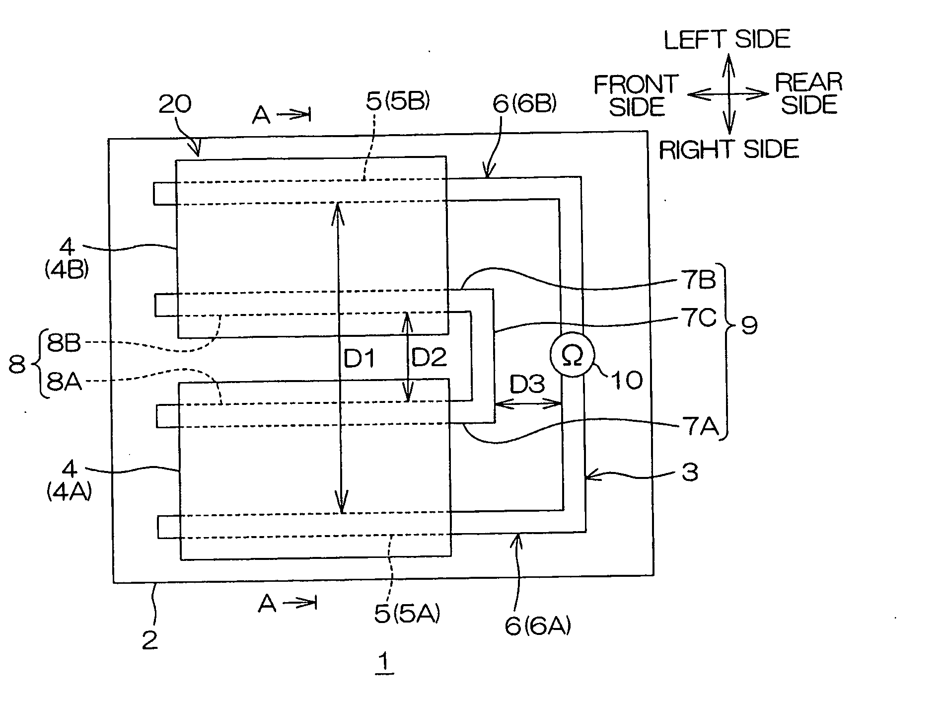
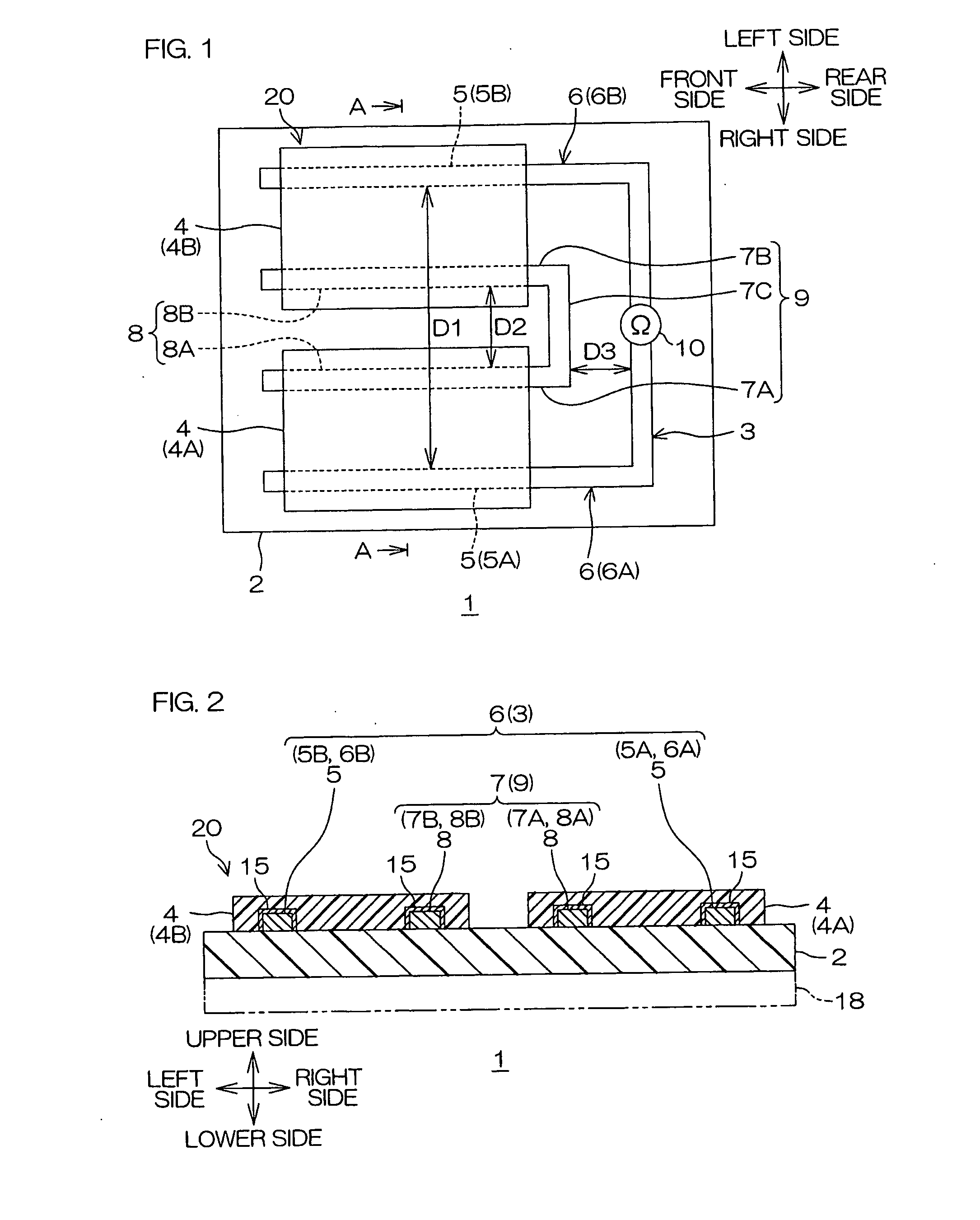
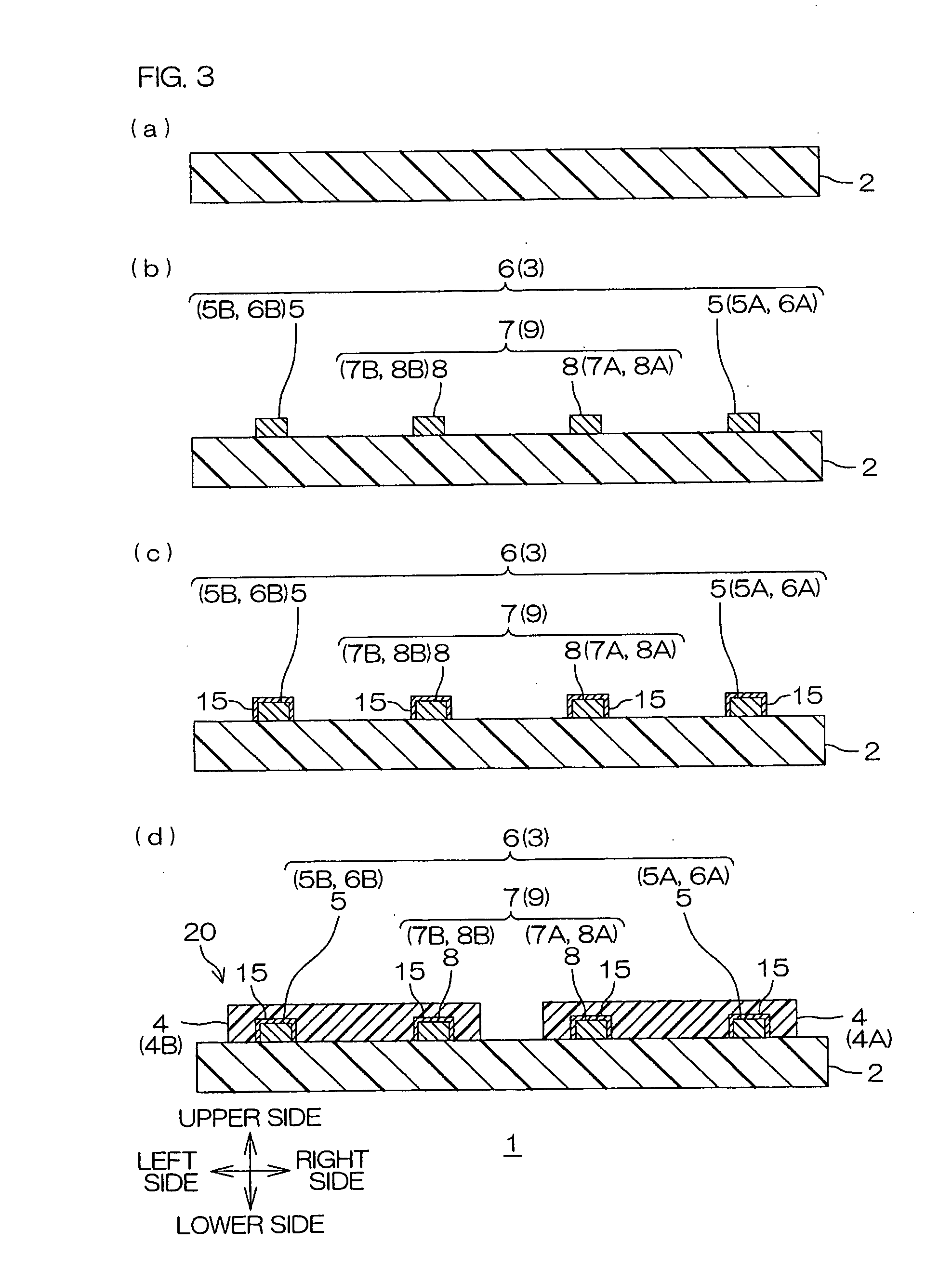
[0172]A liquid crystal polymer copper-clad laminate (product number: ESPANEX L-12-25-00NE, single-sided, standard type, manufactured by Nippon Steel Chemical Co., Ltd.) in which a 12 μm-thick copper foil as a conductive layer was preliminarily laminated on the upper surface of a 25 μm-thick liquid crystal polymer sheet as an insulating layer was prepared, and an electrode pattern and a bridge wire having the above-mentioned pattern were simultaneously formed by a subtractive method (see FIGS. 1 and 3(b)).

[0173]Each of the first and the second electrode wires had a length of 20 mm and a width of 0.25 mm, and a spacing (D1) between the first and the second electrode wires was 5 mm. The bridge wire had a width of 0.25 mm, each of the first and the second connecting wires had a length of 19 mm, and a spacing (D2) therebetween was 2.5 mm. Each of a spacing between the first electrode wire and the first connecting wire and a spacing between the second electrode wire and the second connect...

example 2

[0179]The gas detection sensor was produced in the same manner as in Example 1 except that two bridge wires were formed in place of one bridge wire, and that three conductive layers (a first conductive layer, a second conductive layer, and a third conductive layer) were formed in place of two conductive layers (the first and the second conductive layers) (see FIG. 4).

[0180]Incidentally, the spacing (D2) between the first connecting wire and the second connecting wire in each of the bridge wires was 1.65 mm, and each of the spacing between the first electrode wire and the first connecting wire of the first bridge wire, the spacing between the second electrode wire and the second connecting wire of the second bridge wire, and the spacing between the second connecting wire of the first bridge wire and the first connecting wire of the second bridge wire was 1.3 mm.

[0181]Further, the conductive component-containing liquid was sprayed three times. A mask having an opening (opening area of...

example 3

[0182]The gas detection sensor was produced in the same manner as in Example 2 except that the shape of the bridge wire was changed from a generally U-shape in plane view to the shape of a thin flat sheet (see FIG. 5).

[0183]Incidentally, the bridge wire was formed so that its outer shape was the same as the outer peripheral edge of the bridge wire in Example 2.


PUM


Abstract

A substance detection sensor includes an insulating layer; two electrodes spaced in opposed relation to each other on the insulating layer; and conductive layers formed between the two electrodes on the insulating layer so as to electrically connect the two electrodes, and of which a swelling ratio varies depending on the type and / or amount of a specific gas. The conductive layers are formed by dividing into plural layers between the two electrodes.

Description

CROSS REFERENCE TO RELATED APPLICATION[0001]This application claims priority from Japanese Patent Application No. 2009-5091, filed Jan. 13, 2009, the content of which is herein incorporated by reference in its entirety.BACKGROUND OF THE INVENTION[0002]1. Field of the Invention[0003]The present invention relates to a substance detection sensor, and more particularly to a substance detection sensor for mainly detecting the type or amount of gas.[0004]2. Description of Related Art[0005]Heretofore, material sensors for detecting gas or liquid have been used in various industrial applications. The material sensor is used for qualitative and quantitative analysis of specific gases or liquids.[0006]For example, there have been proposed sensor arrays including a resistor containing a conductive substance, and first and second conductive leads spaced apart from each other and electrically coupled via the resistor (cf. Japanese Unexamined Patent Publication No. 2006-10703).[0007]In the sensor...

Claims


Application Information

Patent Timeline
Patent Type & Authority Applications(United States)
IPC IPC(8): G01R27/08
CPCG01N27/125G01R27/08G01N27/126
Inventor YAMAZAKI, HIROSHINAITO, TOSHIKIHANAZONO, HIROYUKI
Owner NITTO DENKO CORP
Why Eureka
Try Eureka