
Diffractive optical relay device with improved color uniformity

a technology of diffractive optical relay and color uniformity, applied in the field of optical relay, can solve the problems of low chromatic sensitivity at 2 nm spectral range becoming unacceptable sensitivity, uniform optical output across the grating, and radiation into the air being uniform across the grating, so as to improve the performance of devices and systems, and reduce color aberration over a part of the beam's cross section.

Inactive Publication Date: 2010-07-15
MIRAGE INNOVATIONS
View PDF77 Cites 206 Cited by
  • Summary
  • Abstract
  • Description
  • Claims
  • Application Information

AI Technical Summary

Benefits of technology

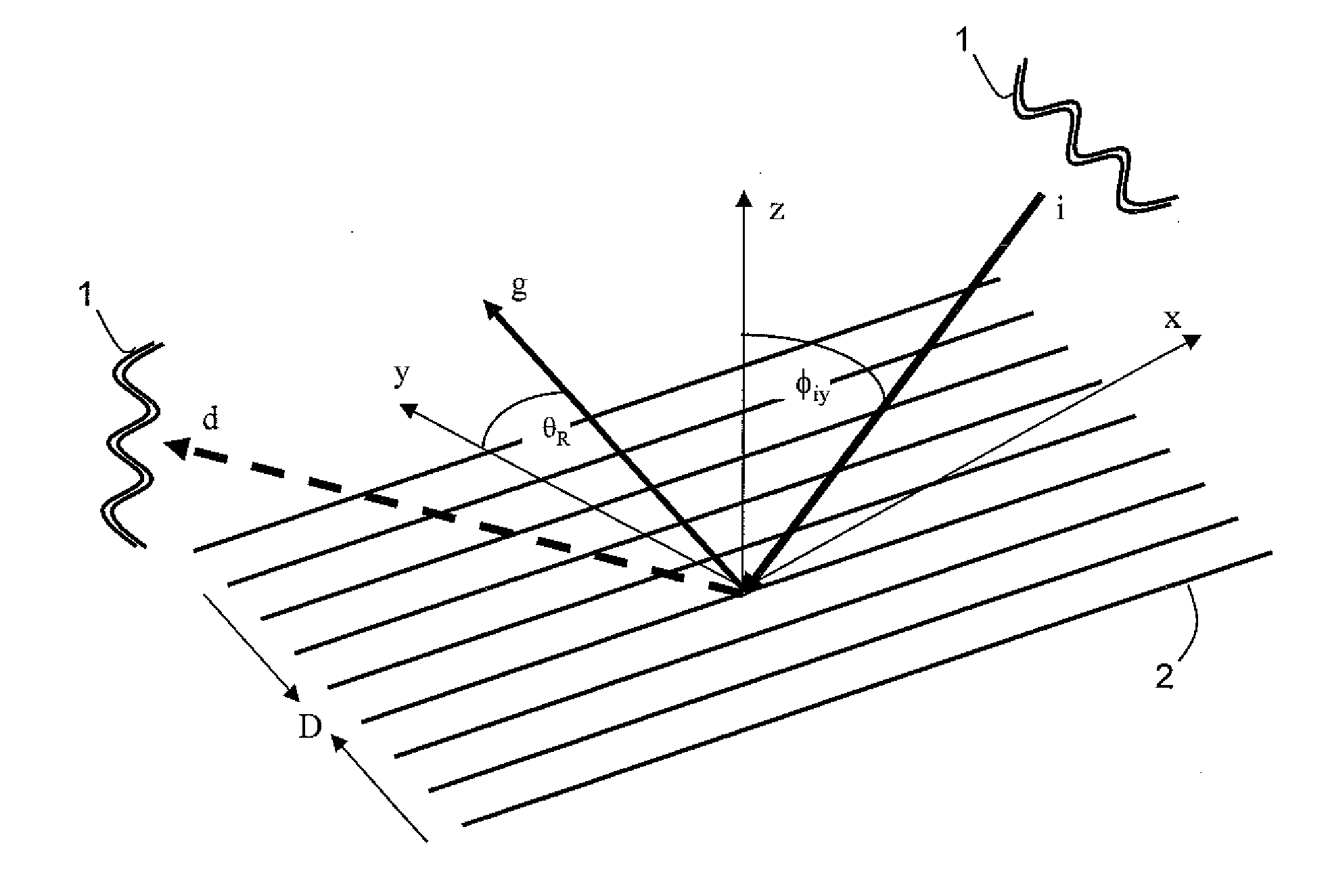
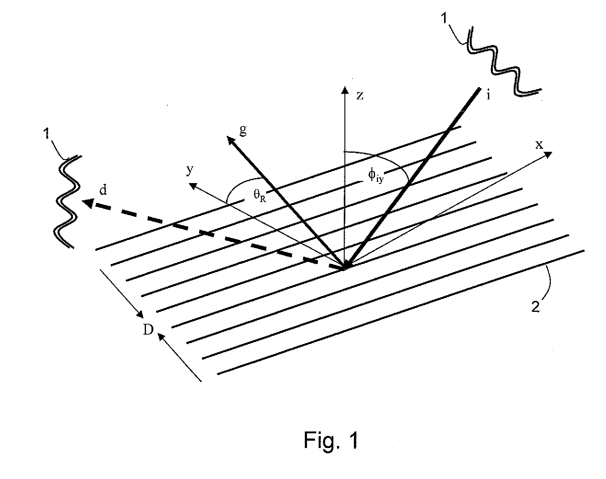
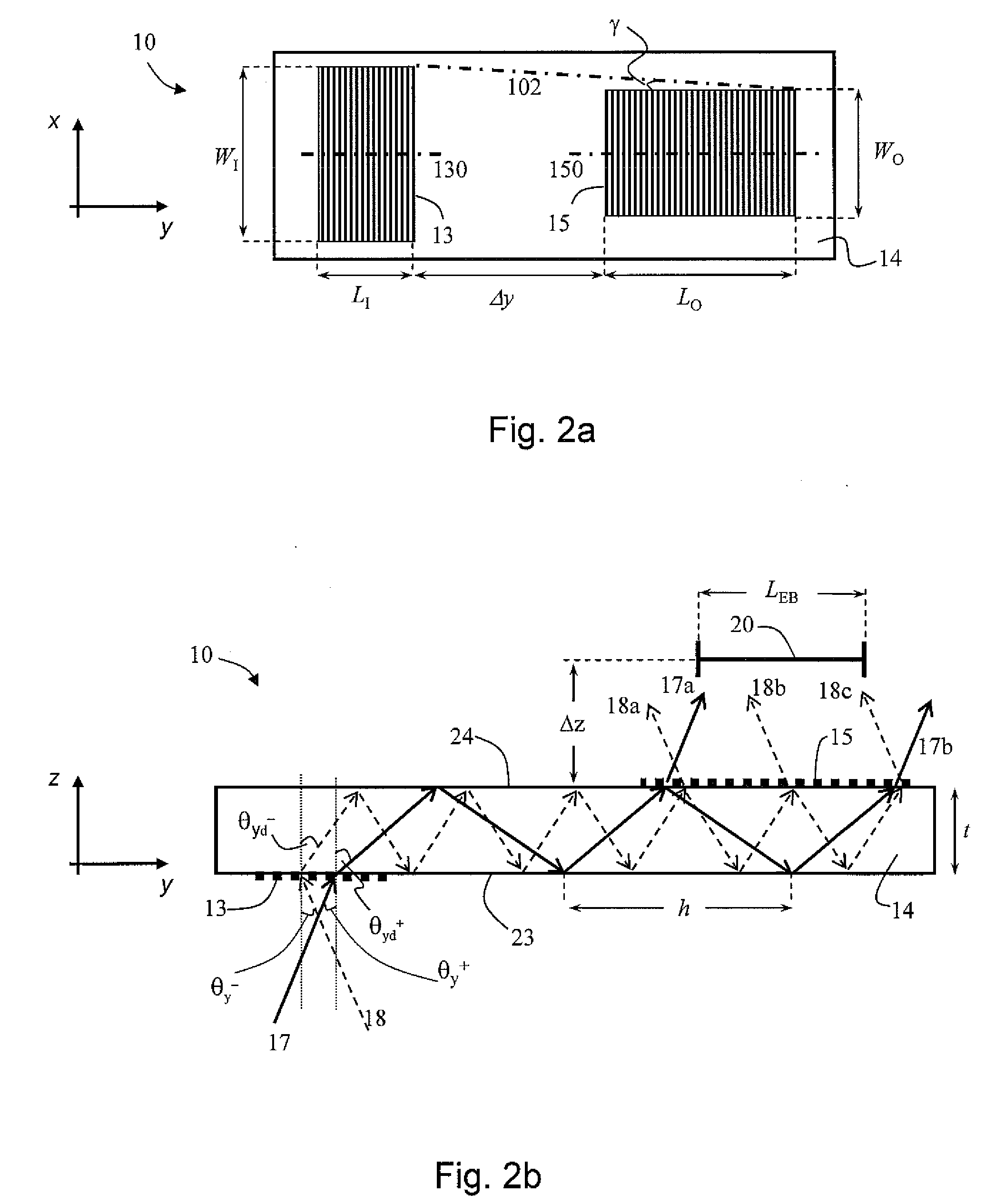
[0018]The present inventors have discovered a technique for providing a light beam having low color aberrations. It was uncovered by the present inventors, that when a light beam is transmitted by an optical device, it is sufficient to ensure low color aberrations over a part of the beam's cross section. The present inventors have demonstrated that this can considerably improve the performances of devices and systems employing diffractive optics.
[0024]In some embodiments of the present invention, two or more relay devices are used for transmitting a light beam. This is particularly useful when it is desired to transmit chromatic light beam. In such embodiments, different sub-spectra can be relayed by different devices. This can reduce optical losses, because each relay device can be optimized according to the sub-spectrum relayed thereby.

Problems solved by technology

However, the diffractive collimating element of Friesem et al. is known to narrow spectral response, and the low chromatic sensitivity at spectral range of ±2 nm becomes an unacceptable sensitivity at ±20 nm or ±70 nm.
As a result, the optical output across the grating is not uniform.
The spatial control of the emitted intensity in the grating plane is achieved by variations in the grating duty cycle and the radiation into the air is not uniform across the grating.

Method used


Image

  • Diffractive optical relay device with improved color uniformity
  • Diffractive optical relay device with improved color uniformity
  • Diffractive optical relay device with improved color uniformity

Examples


examples

[0285]Reference is now made to the following examples, which together with the above descriptions, illustrate the invention in a non limiting fashion.

[0286]In accordance with some embodiments of the present invention, three types of optical apparatus, referred to as types I, II and III, were designed. Each apparatus was designed to include two optical relay devices, each having a light-transmissive substrate formed with one input diffraction grating and two output diffraction grating, as illustrated in FIG. 12.

[0287]In each apparatus, the first relay device 322a (lower device in FIG. 12) was designated to relay blue and near blue light, and the second relay device 322b (upper device in FIG. 12) was designated to relay red and near red light. All gratings had binary profiles, with ridges which are leveled with the surfaces of the substrates.

[0288]In all three types of apparatus, the thickness of each substrate was 2.3 mm and the index of refraction of each substrate was 1.51. The dis...


PUM


Abstract

An optical relay comprises a light-transmissive substrate having a plurality of diffractive optical elements, where at least one diffractive optical element is characterized by nonuniform diffraction efficiency. The substrate and diffractive optical elements are designed and constructed to relay at least a portion of a light beam emanating from an object to at least one predetermined eye-box in a manner such that for each point of the object, there is a set of parallel outgoing light rays originating from the point and arriving to the eye-box. The color difference between any two parallel light rays of the set is less than 50 ΔE* units.

Description

FIELD AND BACKGROUND OF THE INVENTION[0001]The present invention relates to optics and, more particularly, to a diffractive optical relay device.[0002]Miniaturization of electronic devices has always been a continuing objective in the field of electronics. Electronic devices are often equipped with some form of a display, which is visible to a user. As these devices reduce in size, there is an increase need for manufacturing compact displays, which are compatible with small size electronic devices. Besides having small dimensions, such displays should not sacrifice image quality, and be available at low cost. By definition the above characteristics are conflicting and many attempts have been made to provide some balanced solution.[0003]An electronic display may provide a real image, the size of which is determined by the physical size of the display device, or a virtual image, the size of which may extend the dimensions of the display device.[0004]A real image is defined as an image...

Claims


Application Information

Patent Timeline
IPC IPC(8): G02B5/18
CPCG02B6/0038G02B6/0058G02B2027/0116G02B27/0103G02B2027/011G02B27/0081
Inventor COHEN, YORAMELDAR, AMIRAMNEISTEIN, EYALITZKOVITCH, MOTIAVIEL, YUVAL
Owner MIRAGE INNOVATIONS
Learn More