Wiring connecting structure for piezoelectric actuator, piezoelectric actuator, and head suspension

a piezoelectric actuator and connecting structure technology, applied in the field of piezoelectric actuator wiring connecting structure, piezoelectric actuator wiring connection structure, piezoelectric actuator wiring connection structure, and head suspension, can solve the problem of deteriorating the reliability of electric connection to the piezoelectric element, the risk of cracking of the related art, and the insufficient bonding strength to achieve the effect of reducing the risk of cracking of the piezoelectric element,

Active Publication Date: 2010-07-15
NHK SPRING CO LTD
View PDF10 Cites 62 Cited by
  • Summary
  • Abstract
  • Description
  • Claims
  • Application Information

AI Technical Summary

Benefits of technology

[0019]Consequently, the above-mentioned aspect can perform wiring to the piezoelectric el

Problems solved by technology

An important issue for the head suspension employing the dual actuator system is how to supply electricity to the piezoelectric elements.
This related art has a risk of cracking the piezoelectric element because, to secure a bonding strength, it applies a local stress on the brittle piezoelectric element when bonding the wire to the piezoelectric

Method used


Image

  • Wiring connecting structure for piezoelectric actuator, piezoelectric actuator, and head suspension
  • Wiring connecting structure for piezoelectric actuator, piezoelectric actuator, and head suspension
  • Wiring connecting structure for piezoelectric actuator, piezoelectric actuator, and head suspension

Examples


embodiment 1

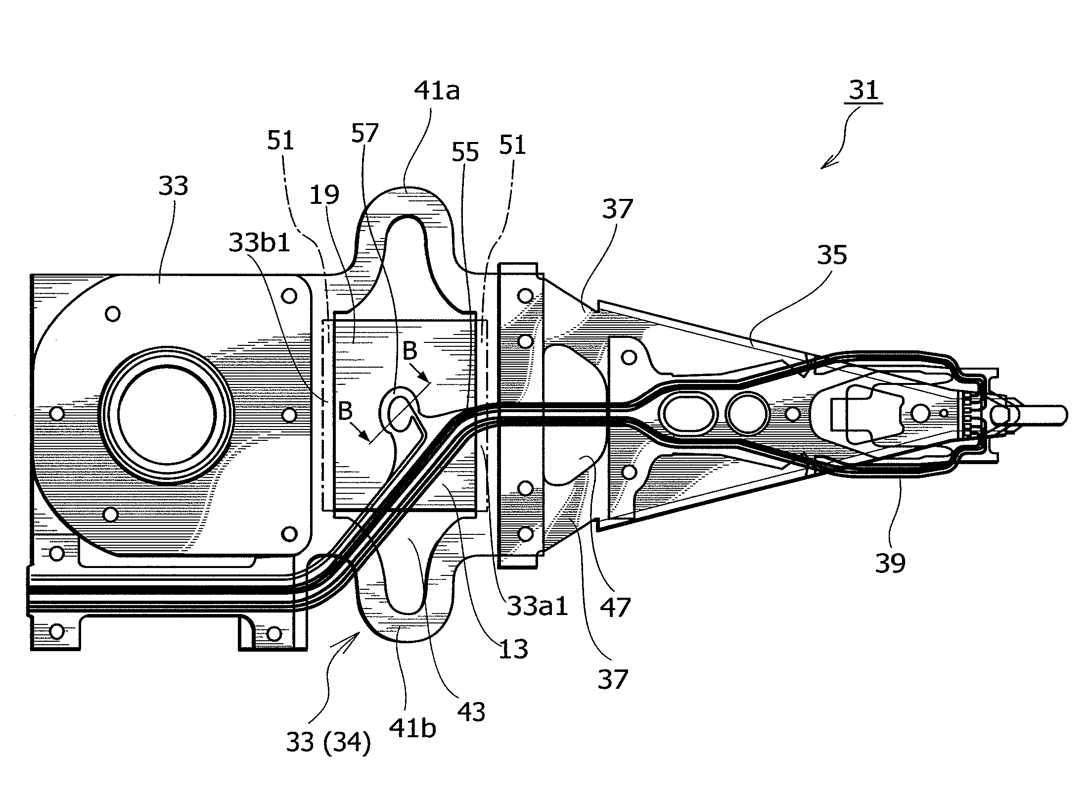
[0072]FIGS. 5A and 5B are views illustrating the wiring member 55 of the head suspension 31 of FIG. 1, in which FIG. 5A is a view seen from below the head suspension 31 and FIG. 5B is a view seen from the piezoelectric element 13 embedded in the head suspension 31. FIGS. 6A and 6B are views illustrating a terminal 57-1 of the present invention, in which FIG. 6A is a front view seen from the piezoelectric element 13 side and FIG. 6B is a sectional view of an attached state taken along the line B-B of FIG. 4.

[0073]When assembling the head suspension 31, the piezoelectric element 13 is positioned with respect to an inner circumference of the opening 43, so that the common electrode 19 (corresponding to the “electrode surface” stipulated in the claims) of the piezoelectric element 13 faces a terminal 57 of the wiring member 55 of the flexure 39 as illustrated in FIGS. 4, 5A, and 5B. Between the terminal 57 of the flexure 39 and the common electrode 19 of the piezoelectric element 13, t...

embodiment 2

[0110]A wiring connecting structure for a piezoelectric actuator will be explained. This wiring connecting structure employs a terminal 57-2 illustrated in FIGS. 8A and 8B in which FIG. 8A is a front view seen from the piezoelectric element 13 side and FIG. 8B is a sectional view of an attached state taken along the line B-B of FIG. 4.

[0111]The terminal 57-2 according to Embodiment 2 includes a first liquid stopper 69-2 having an annular shape around the through hole 67 in a gap between the common electrode 19 and the terminal 57-2. Around the first liquid stopper 69-2, there is arranged a second liquid stopper 101 that is annular, has different diameter from the first liquid stopper 69-2, and is concentric with the first liquid stopper 69-2. An annular recess between the first and second liquid stoppers 69-2 and 101 defines a trapping space 77 of a liquid trap 73.

[0112]If the liquid conductive adhesive 79 filled in the through hole 67 is excessive and if the excess overflows the f...

embodiment 3

[0118]A wiring connecting structure for a piezoelectric actuator of the present invention will be explained. This wiring connecting structure employs a terminal 57-3 illustrated in FIGS. 9A and 9B in which FIG. 9A is a front view seen from the piezoelectric element 13 side and FIG. 9B is a sectional view of an attached state taken along the line B-B of FIG. 4.

[0119]The terminal 57-3 according to Embodiment 3 includes a first liquid stopper 69-3 having an annular shape around the through hole 67 in a gap between the common electrode 19 and the terminal 57-3. Around the first liquid stopper 69-3, there is arranged a second liquid stopper 101 that is annular, has different diameter from the first liquid stopper 69-3, and is concentric with the first liquid stopper 69-3. A circumferential part of the first liquid stopper 69-3 has a cut 103 that is characteristic to Embodiment 3.

[0120]An annular recess between the first and second liquid stoppers 69-3 and 101 defines a trapping space 77...


PUM


Abstract

A wiring connecting structure for a piezoelectric actuator includes a terminal 57-1, a through hole 67 formed through the terminal 57-1, a first liquid stopper 69-1 arranged around the through hole 67 in a gap between the terminal 57-1 and a common electrode 19 of a piezoelectric element 13 of the piezoelectric actuator, and a liquid trap 73 arranged adjacent to the first liquid stopper 69-1. The terminal 57-1 faces the common electrode 19 with an electric insulating layer 61 being on the piezoelectric element 13 side and the first liquid stopper 69-1 being in the gap between the common electrode 19 and the terminal 57-1. A liquid conductive adhesive 79 is filled in the through hole 67. If there is an excess of the liquid adhesive 79, the excess is guided into a trapping space 77 of the liquid trap 73, to prevent the excess from oozing out.

Description

BACKGROUND OF THE INVENTION[0001]1. Field of the Invention[0002]The present invention generally relates to a piezoelectric actuator having a piezoelectric element that warps in response to applied electric power to minutely move an objective part relative to a base part. In particular, the present invention relates to a wiring connecting structure capable of achieving wiring to the piezoelectric element without damaging the piezoelectric element or deteriorating the reliability thereof. The present invention also relates to the piezoelectric actuator and a head suspension employing the piezoelectric actuator.[0003]2. Description of Related Art[0004]Small-sized, precision information devices are rapidly advancing, and for use with such devices, needs for micro-actuators capable of conducting positioning control for very small distances are increasing. Such micro-actuators are highly needed by, for example, optical systems for correcting focuses and inclination angles, ink jet printer...

Claims


Application Information

Patent Timeline
IPC IPC(8): G11B21/24H02N2/06
CPCG11B5/4833G11B5/4873H01L41/29H01L41/0475H01L41/0986G11B5/556H10N30/875H10N30/206H10N30/06
Inventor FUCHINO, HIDEKI
Owner NHK SPRING CO LTD
Why Eureka
Try Eureka