Discharge lamp lighting apparatus

a technology of discharge lamp and lighting apparatus, which is applied in the direction of electric variable regulation, process and machine control, instruments, etc., can solve the problems of sudden brightness change of discharge lamp, delay in the response of feedback control loop with respect, and breakage of switching elements or transformers, so as to speed up the response of feedback control loop and improve the reliability of discharge lamp. , the effect of easy realizing a soft start operation

Inactive Publication Date: 2011-07-19
SANKEN ELECTRIC CO LTD
View PDF3 Cites 13 Cited by
  • Summary
  • Abstract
  • Description
  • Claims
  • Application Information

AI Technical Summary

Benefits of technology

[0009]On the other hand, speeding up the response of the feedback control loop with respect to a change in a current passed through the load with the use of the capacitor results in making the inclination of the soft start operation steeper at the start of an ON interval of the burst dimming operation, i.e., at the time when the switch circuit starts to carry out an ON / OFF operation according to a burst dimming signal. Such a steep inclination of the soft start operation causes a surge in a current passed to the discharge lamp, to cause noise on a display and deteriorate the reliability of the discharge lamp.
[0010]According to the present invention, a discharge lamp lighting apparatus capable of easily realizing a soft start operation at the start of each ON interval in a burst dimming operation can be provided.

Problems solved by technology

Due to this, making the inclination of the soft start operation gentler by the capacitor at the start of an ON interval of the burst dimming operation results in delaying response of a feedback control loop with respect to a change in a current passed through the load.
As a result, a sudden load change or a sudden input change may cause a sudden brightness change of the discharge lamp, and in some cases, may break the switching elements or the transformer.
On the other hand, speeding up the response of the feedback control loop with respect to a change in a current passed through the load with the use of the capacitor results in making the inclination of the soft start operation steeper at the start of an ON interval of the burst dimming operation, i.e., at the time when the switch circuit starts to carry out an ON / OFF operation according to a burst dimming signal.
Such a steep inclination of the soft start operation causes a surge in a current passed to the discharge lamp, to cause noise on a display and deteriorate the reliability of the discharge lamp.

Method used


Image

  • Discharge lamp lighting apparatus
  • Discharge lamp lighting apparatus
  • Discharge lamp lighting apparatus

Examples


first embodiment

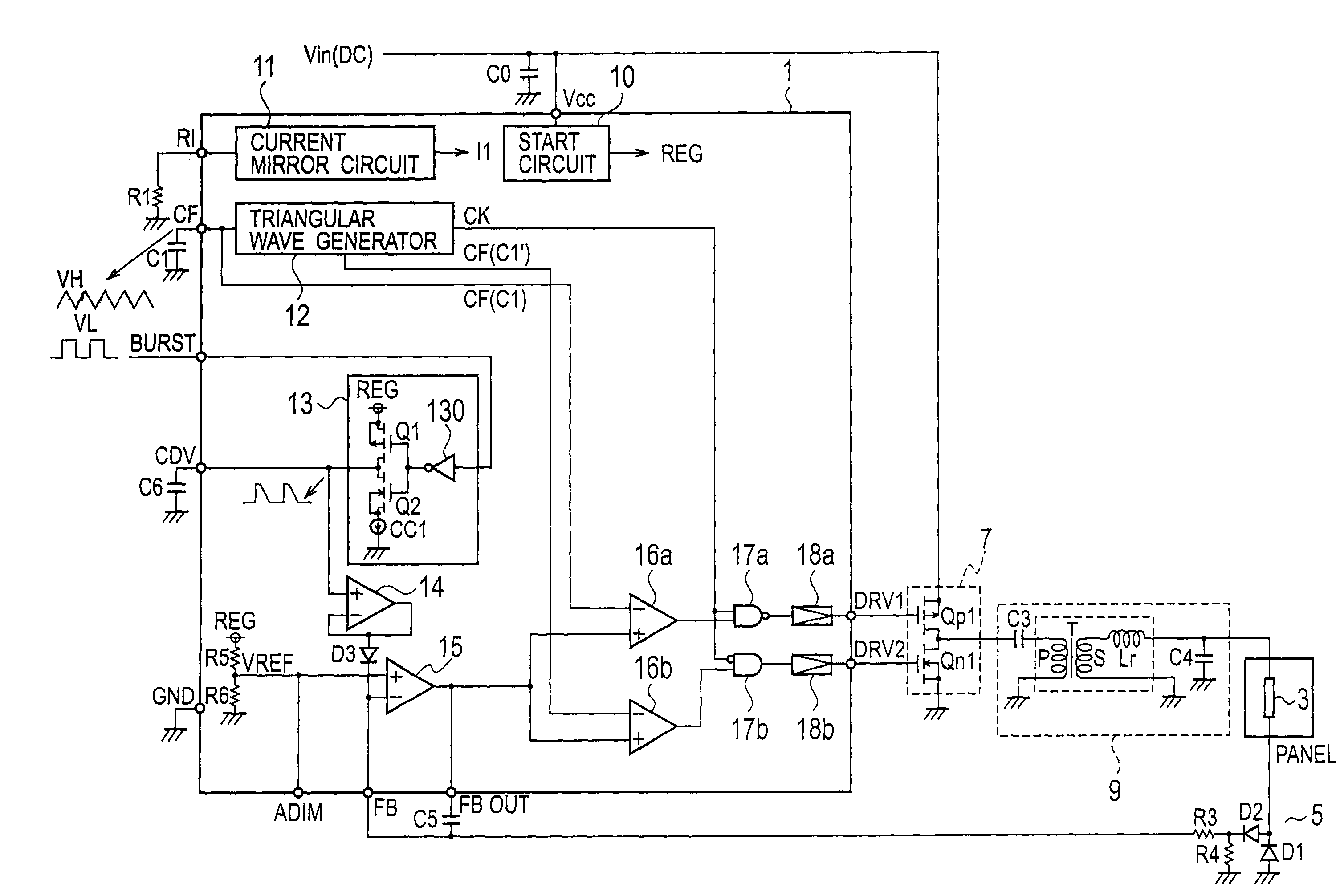
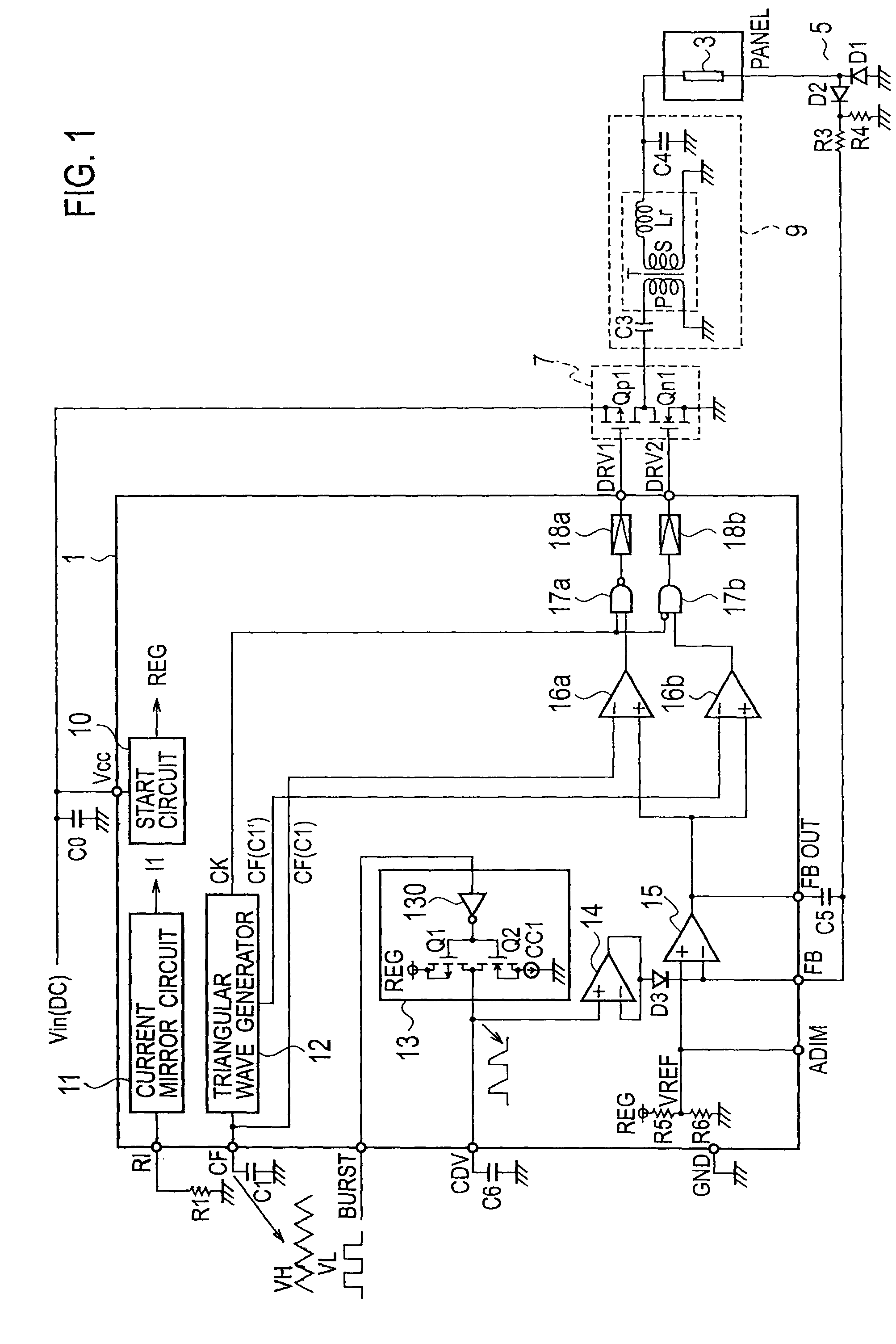
[0023]FIG. 1 is a circuit diagram illustrating a discharge lamp lighting apparatus according to the first embodiment. The apparatus of FIG. 1 includes, between a DC power source Vin and the ground, a series circuit including a high-side p-type MOSFET Qp1 (hereinafter referred to as “p-type FET Qp1”) and a low-side n-type MOSFET Qn1 (hereinafter referred to as “n-type FET Qn1”). Between a connection point of the p-type and n-type FETs Qp1 and Qn1 and the ground, there is a series circuit including a capacitor C3 and a primary winding P of a transformer T. Ends of a secondary winding S of the transformer T are connected to a capacitor C4. A reactor Lr is a leakage inductance of the transformer T.

[0024]A source of the p-type FET Qp1 receives the DC power source Vin and a gate thereof is connected to a terminal DRV1 of a control circuit 1. A gate of the n-type FET Qn1 is connected to a terminal DRV2 of the control circuit 1.

[0025]The control circuit 1 includes a start circuit 10, a curr...

second embodiment

[0055]FIG. 3 is a circuit diagram illustrating a discharge lamp lighting apparatus according to the second embodiment of the present invention. The second embodiment employs an inclination generator 13a that includes an inverter 130, a p-type FET Q1, an n-type FET Q2, and a constant current source CC1 that is arranged between a power source REG and the p-type FET Q1.

[0056]A connection point of the p-type and n-type FETs Q1 and Q2 is connected through a terminal CDV to an inclination determining capacitor C6, and also, is connected to a positive (+) terminal of a buffer 14a that is a voltage follower. A negative (−) terminal of the buffer 14a and an output terminal thereof are connected to each other. A connection point of the negative and output terminals of the buffer 14a is connected through a diode D3 to a positive (+) terminal of an error amplifier 15. The positive terminal of the error amplifier 15 is also connected to a connection point of resistors R5 and R6.

[0057]The error a...

third embodiment

[0063]FIG. 4 is a circuit diagram illustrating a discharge lamp lighting apparatus according to the third embodiment of the present invention. The third embodiment of FIG. 4 connects an inclination determining capacitor C6 to an output of a voltage divider (R5, R6) in parallel with the resistor R6. The third embodiment employs an n-type FET Q3 whose gate receives a burst dimming signal and whose drain is connected through a diode D3 to a connection point of the resistors R5 and R6, i.e., an output point of the voltage divider.

[0064]When the burst dimming signal is high, the n-type FET Q3 turns on to short-circuit the inclination determining capacitor C6 through the diode D3, so that a positive (+) terminal of an error amplifier 15 instantaneously becomes nearly zero. This makes a negative (−) terminal of the error amplifier 15 low to zero a current passed through a discharge lamp 3.

[0065]When the burst dimming signal is low, the n-type FET Q3 turns off to charge the inclination dete...


PUM


Abstract

A discharge lamp lighting apparatus includes a switch circuit for DC / AC converting, a discharge lamp connected to a secondary winding of a transformer, a current detector detecting an AC output current of the discharge lamp, an error amplifier outputting an error signal to a detected current, a control circuit generating control signals that turn on / off the switching elements in such a way as to control the AC output current at a predetermined value, and a time division signal generator generating a time division signal at the start of an ON / OFF operation of the switching elements, wherein the time division signal delays a change in a burst dimming signal or has a predetermined inclination on the burst dimming signal. The error amplifier changes the error signal according to the time division signal from the time division signal generator.

Description

BACKGROUND OF THE INVENTION[0001]1. Field of the Invention[0002]The present invention relates to a discharge lamp lighting apparatus for lighting a discharge lamp used for, for example, a liquid crystal display unit.[0003]2. Description of the Related Art[0004]There is a discharge lamp lighting apparatus that employs a burst dimming pulse signal to control the brightness of a discharge lamp to a desired level. This apparatus starts and stops an ON / OFF operation of switching elements such as p-type and n-type FETs according to the burst dimming pulse signal, thereby controlling the brightness of the discharge lamp.[0005]There is a discharge lamp lighting apparatus of this type that conducts a soft start operation during a burst dimming operation. An example of this type of discharge lamp lighting apparatus is described in Japanese Unexamined Patent Application Publication No. 2004-166446. The apparatus of this related art employs a transformer having a primary winding connected to a ...

Claims


Application Information

Patent Timeline
Patent Type & Authority Patents(United States)
IPC IPC(8): H05B31/30
CPCH05B41/3927H05B41/14
Inventor KIMURA, KENGO
Owner SANKEN ELECTRIC CO LTD
Why Eureka
Try Eureka