Microphone preamplifier circuit and voice sensing devices

a microphone preamplifier and circuit technology, applied in the direction of transducer details, electrical transducers, microphone structural associations, etc., can solve the problem of affecting the quality of microphone preamplifiers

Inactive Publication Date: 2010-07-15
FORTEMEDIA
View PDF7 Cites 8 Cited by
  • Summary
  • Abstract
  • Description
  • Claims
  • Application Information

AI Technical Summary

Problems solved by technology

Thus, quality of microphone preamplifiers is hindered due to the circuit structure.

Method used


Image

  • Microphone preamplifier circuit and voice sensing devices
  • Microphone preamplifier circuit and voice sensing devices
  • Microphone preamplifier circuit and voice sensing devices

Examples


Embodiment Construction

[0014]The following description is of the best-contemplated mode of carrying out the invention. This description is made for the purpose of illustrating the general principles of the invention and should not be taken in a limiting sense. The scope of the invention is best determined by reference to the appended claims.

[0015]A system on chip solution is proposed to minimize noise and interference introduced by off chip components and physical layout of the system on chip.

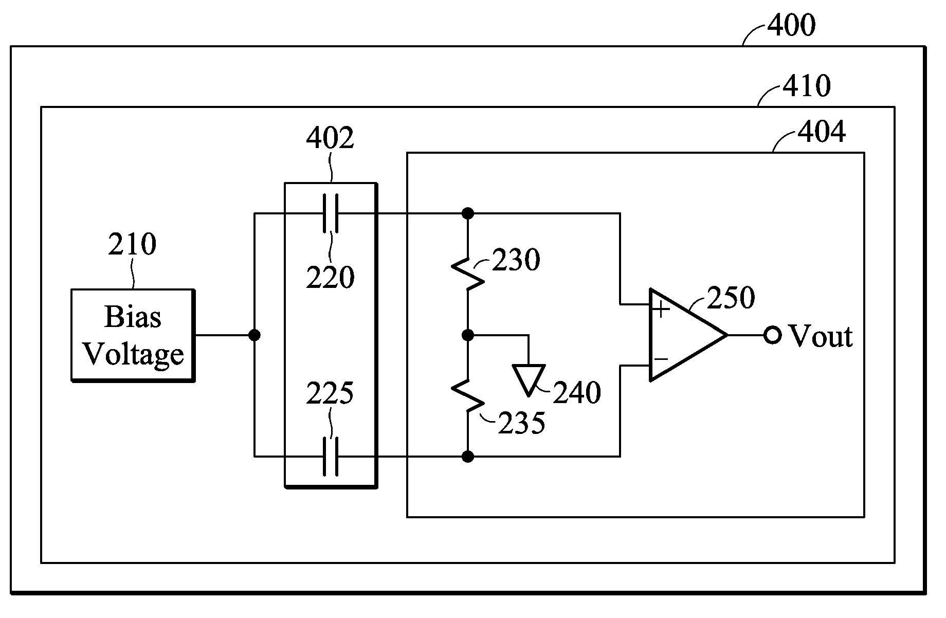
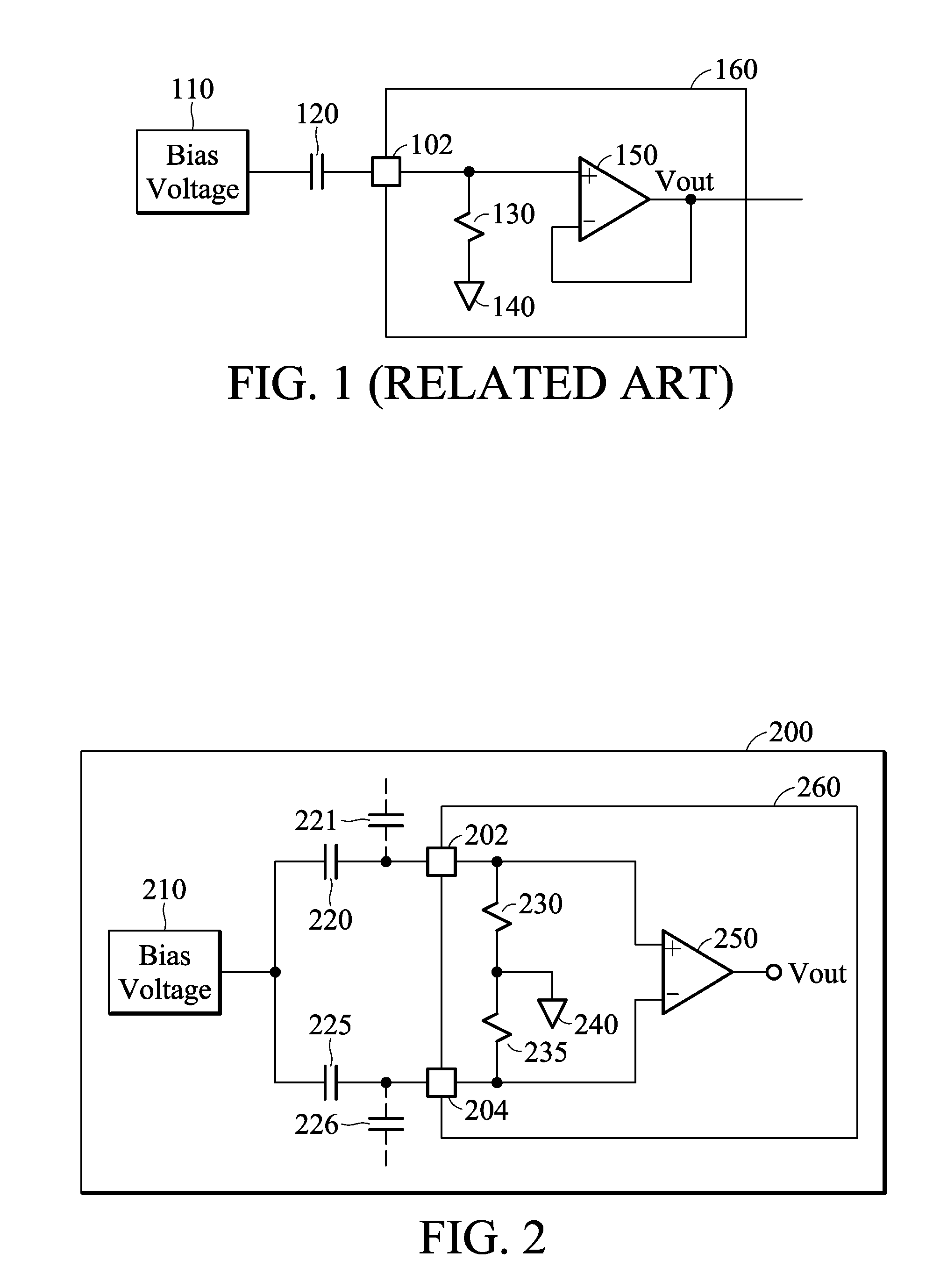
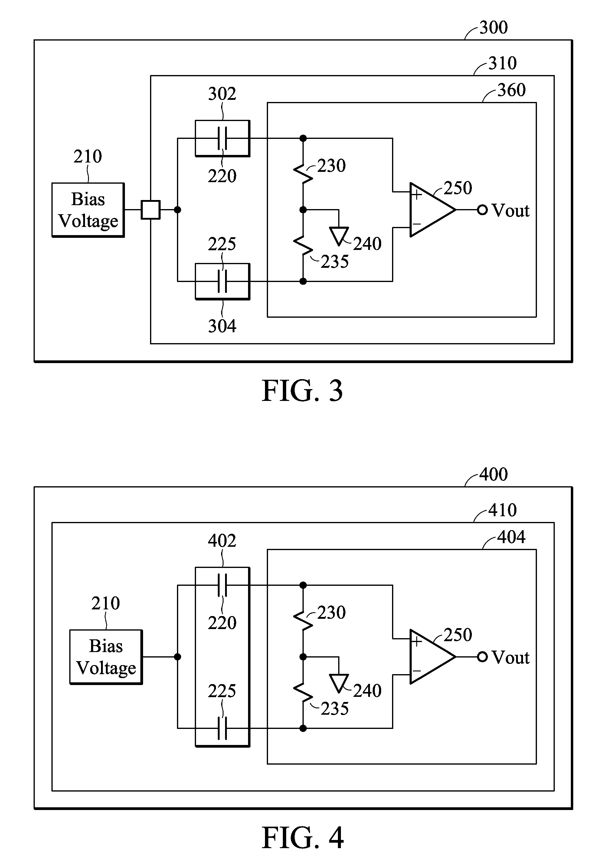
[0016]FIG. 2 shows another embodiment of a voice sensing device according to the invention. The voice sensing device is typically implemented on a circuit board 200. The voice sensing device may be a various type portable device such as a digital audio recorder, a mobile phone, or a camera. The circuit board 200 is usually referred to as a Printed Circuit Board (PCB). In the circuit board 200, a system on chip 260 with two pads 202 and 204 is implemented. A preamplifier circuit is implemented partially within the sys...


PUM


Abstract

A microphone preamplifier circuit is provided in a system on chip. An amplifier comprises a first input end, a second input end, and an output end. A bias voltage is provided by a bias voltage source. A first sensor is coupled to the first input end and the bias voltage source for sensing a first physical parameter and a second physical parameter. A second sensor is coupled to the second input end and the bias voltage source for sensing the first physical parameter, wherein the second sensor is insensitive to the second physical parameter. The output end of the amplifier outputs a difference of the first and second input ends whereby noises and interferences are reduced.

Description

BACKGROUND OF THE INVENTION[0001]1. Field of the Invention[0002]The invention relates to a microphone preamplifier, and in particular, to a circuit structure that eliminates interferences within the circuit.[0003]2. Description of the Related Art[0004]FIG. 1 shows a conventional microphone preamplifier circuit. An amplifier 150 is implemented in an integrated chip 160, having a first input end (+), a second input end (−) and an output end. The integrated chip 160 has a pad 102 for coupling signals from outside of the chip to the amplifier 150. Meanwhile, the first input end is biased by a bias resistor 130 and a reference voltage source 140 inside of the chip. A microphone cartridge 120 is coupled between a bias voltage source 110 and the pad 102. The output end of the amplifier 150 is connected to the second input end (−), whereby a pre-amplified result of the microphone cartridge 120 is output (denoted as Vout). The microphone cartridge 120 may be an electret condenser microphone ...

Claims


Application Information

Patent Timeline
Patent Type & Authority Applications(United States)
IPC IPC(8): H04R3/00
CPCH04R2201/003H04R1/04
Inventor CHIU, JUI-TEWU, LI-TE
Owner FORTEMEDIA
Why Eureka
Try Eureka