Detachable insert-type cutting tool

Active Publication Date: 2010-07-15
MITSUBISHI MATERIALS CORP
View PDF21 Cites 22 Cited by
  • Summary
  • Abstract
  • Description
  • Claims
  • Application Information

AI Technical Summary

Benefits of technology

[0014]According to the present invention, since a coolant is supplied from the rake surface to the cutting edge of cutting insert, it is possible to cool and lubricate a site cut by the cutting edge more effectively.
[0015]In the detachable insert-type cutting tool of the present invention, a second groove extending along the first groove of the head member may be formed on the attachment surface of the holder so as to be opened toward the cutting edge of the cutting insert. The coolant hole formed by the first and second grooves is further increased in cross-section

Problems solved by technology

However, the adaptor mounting portion, the supporter, the clamp piece and others are needed for drilling by using a drill or the like to result in an increase in production cost.
H07-227702, when the size of a part to be drilled is restricted depending on the width of a groove formed on the workpiece, it is difficult to drill into the workpiece.
There are also

Method used


Image

  • Detachable insert-type cutting tool
  • Detachable insert-type cutting tool
  • Detachable insert-type cutting tool

Examples


Example

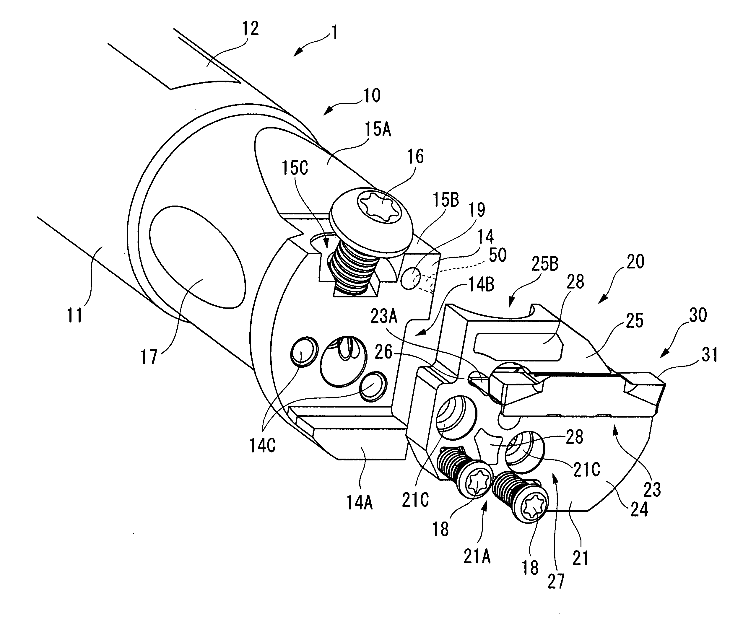
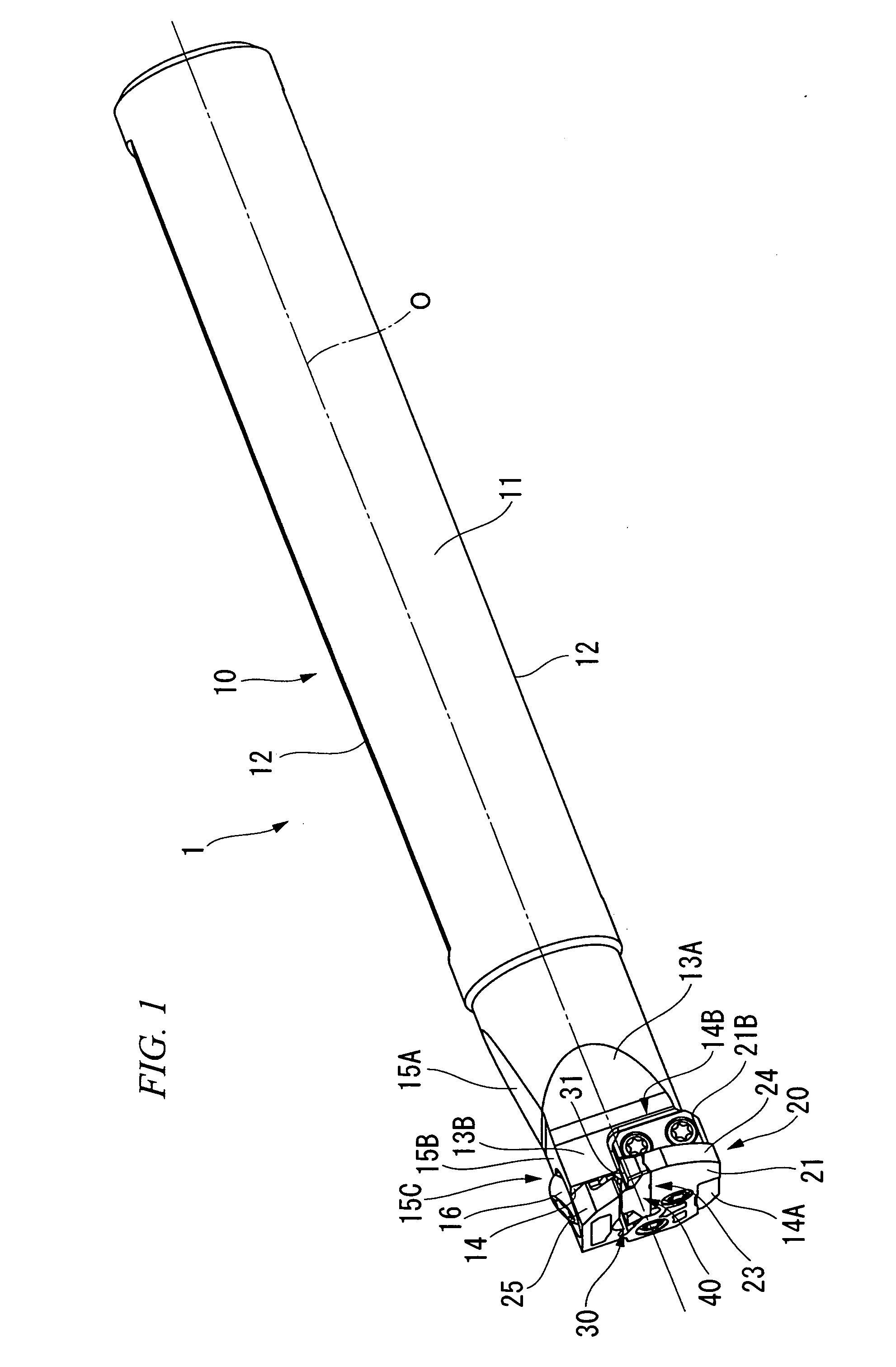
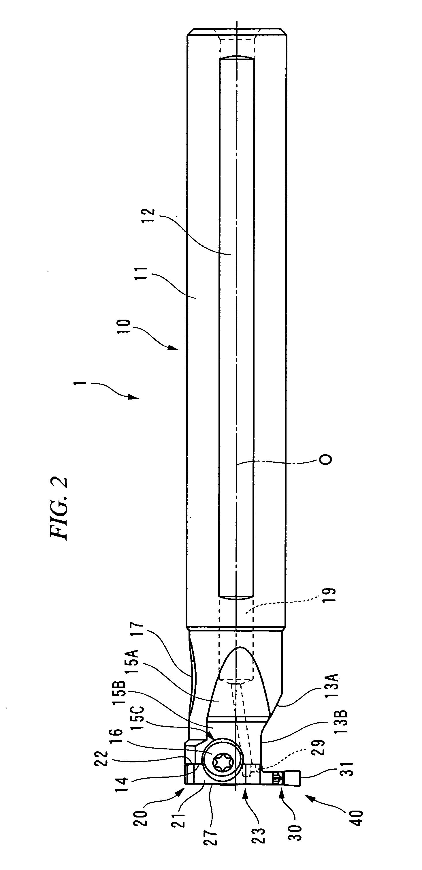
[0025]FIG. 1 to FIG. 8 show one embodiment in which the present invention is applied to a detachable insert-type cutting tool used in inner-diameter processing for groove-forming an inner circumferential surface of a hole formed along the rotating axis of a workpiece which rotates. A main body 1 of the cutting tool in the present embodiment is provided with a holder 10 having an outer shape formed approximately in a cylindrical shape centering around the center axis O and a head member 20 detachably attached to a head portion of the holder 10 (a left-side portion in FIG. 2 and FIG. 4 and a right-side portion in FIG. 3). The head member 20 is provided with a cutting insert 30 having a cutting edge 31 and detachably attached to the head member 20. The cutting edge 31 of the cutting insert constitutes a cutting edge portion 40 which protrudes in one radial direction with respect to the center axis O (a downward direction in FIG. 2, a rightward direction in FIG. 5, and a leftward direct...


PUM


Abstract

The detachable insert-type cutting tool is provided with a holder, a head member which has an insert seat on which a cutting insert is detachably mounted and which is detachably attached to a head portion of the holder so that an attachment surface of the head member is closely in contact with an attachment surface of the holder, a coolant hole which is formed inside the holder so as to be opened on the attachment surface of the holder, and a first groove which is formed on the attachment surface of the head member, communicating with the coolant hole opened on the attachment surface of the holder and extending so as to be opened toward a cutting edge of the cutting insert mounted on the insert seat.

Description

CROSS-REFERENCE TO RELATED APPLICATIONS[0001]Priority is claimed on Japanese Patent Application No. 2008-278307, filed Oct. 29, 2008, the content of which is incorporated herein by reference.BACKGROUND OF THE INVENTION[0002]1. Field of the Invention[0003]The present invention relates to a detachable insert-type cutting tool in which a head member is detachably mounted on a head portion of a holder and a cutting insert is also detachably attached to an insert seat formed on the head member.[0004]2. Description of the Related Art[0005]For example, Published Japanese Translation No. H09-510149 of the PCT International Application has proposed a tool which is able to communicate with coolant supply means for supplying a coolant to the vicinity of a cutting edge, as a tool for cutting the bottom of a hole formed on a workpiece. The tool is provided with a fluid inlet orifice arranged near an adaptor end portion and a fluid outlet orifice arranged at the leading end of an adaptor mounting...

Claims


Application Information

Patent Timeline
IPC IPC(8): B23B27/10B23B27/16
CPCB23B27/007B23B27/10B23B29/043B23B29/046Y10T407/225Y10T407/14Y10T407/2272Y10T407/25Y10T407/2282B23B2220/123
Inventor WATANABE, SHOICHIRONAGAYA, HIDEHIKOASO, NORIOIMAI, YASUHARU
Owner MITSUBISHI MATERIALS CORP
Why Eureka
Try Eureka