
Contra-rotating propeller supported on rudder horn of ship

a technology of rudder horn and propeller, which is applied in the direction of marine propulsion, vessel parts, vessel construction, etc., can solve the problems of reducing the efficiency of the propeller and therefore the thrust of the ship, many restrictions in use, and inconvenient use in general commercial ships. , to achieve the effect of improving the thrust efficiency of the ship, reducing the cost of use, and reducing the energy consumption

Active Publication Date: 2010-07-15
SAMSUNG HEAVY IND CO LTD
View PDF4 Cites 7 Cited by
  • Summary
  • Abstract
  • Description
  • Claims
  • Application Information

AI Technical Summary

Benefits of technology

[0019]As set forth above, the contra-rotating propeller system supported on the rudder horn of a ship according to the present invention provides advantageous effect by minimizing the swirling flow with the contra-rotation of the propellers and thus recovering the energy. Further, it provides the improved thrust efficiency of a ship by simplifying the power transmission structure between the respective propellers with the installation of the epicyclic gear set on the rudder horn and by preventing the contraction of the wake flow in the propeller by employing the ellipsoidal shape of the rudder horn to utilize the hydrodynamic action thereat.

Problems solved by technology

This reduces an efficiency of the propeller and therefore the thrust of a ship.
However, as set forth before, the conventional counter-rotating propeller system requires the dual-propeller shaft structure, the related power transmission system, and a special reverse-rotating device, which is not cost effective to be used in a general commercial ship.
Thus, there are many restrictions in use because of the complexity and the excessive manufacturing cost of the counter-rotating system.
Further, the conventional counter-rotating propellers still have the above problems in that the wake flow 4b has a contracted shape, whereby the propeller efficiency is decreased and thus a thrust of a ship is lowered.

Method used


Image

  • Contra-rotating propeller supported on rudder horn of ship
  • Contra-rotating propeller supported on rudder horn of ship
  • Contra-rotating propeller supported on rudder horn of ship

Examples


first embodiment

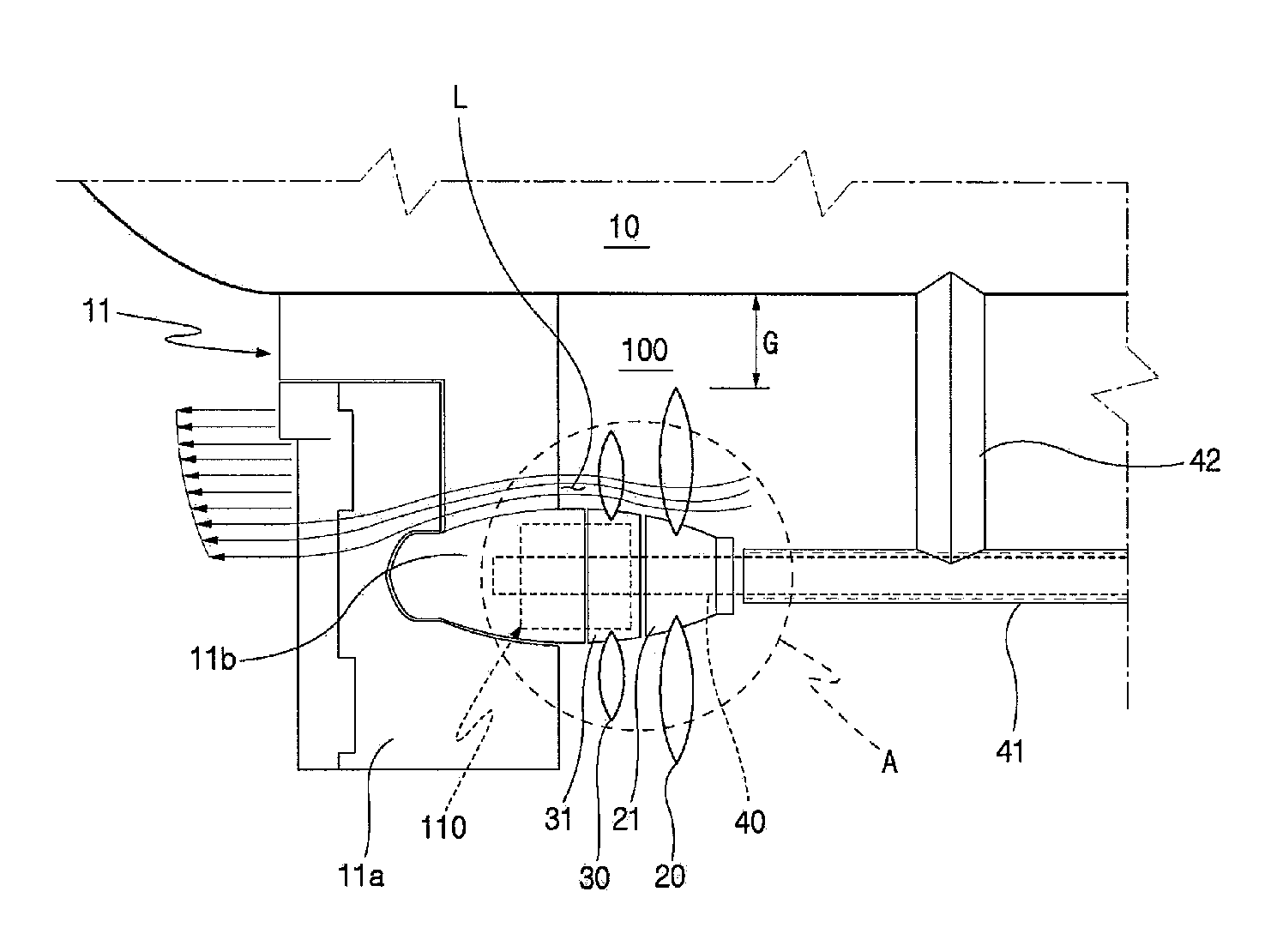
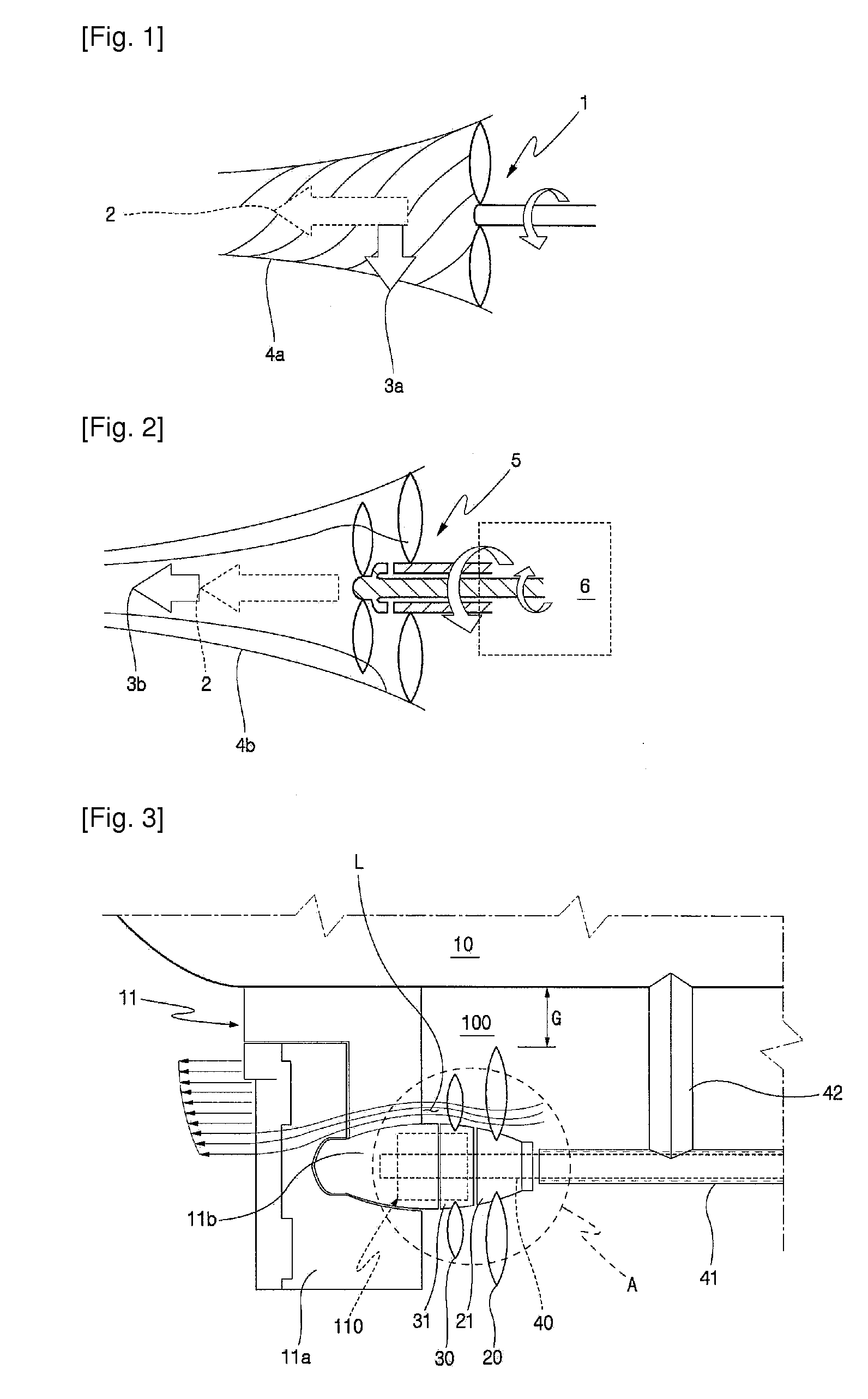
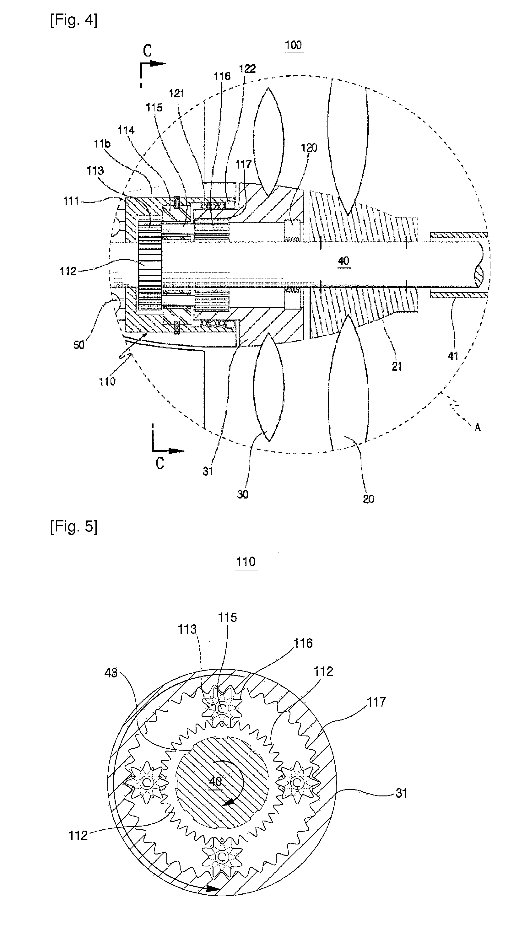
[0029]FIG. 3 is a side view illustrating a contra-rotating propeller system supported on a rudder horn of a ship according to an embodiment of the invention, FIG. 4 is an enlarged sectional view of circle A, shown in FIG. 3, and FIG. 5 is a schematic view illustrating the epicyclic gear set taken along line C-C of FIG. 4.

[0030]As illustrated in FIG. 3, the contra-rotating propeller system 100 in accordance with a first embodiment, supported on the rudder horn of a ship, is designed in order to obviate a high cost special reversible gear and avoid problems associated with the installation of a long hollow shaft member for simultaneous rotation of a plurality of propulsion devices, that is, propellers, on the same shaft.

[0031]A rudder 11 in accordance with the first embodiment has a construction that protrudes vertically downward from the stern-side bottom of a ship 10. The rudder includes a key 11a that is rotatably connected with a rudder stock in a profile body fixed to the ship 10...

second embodiment

[0056]Hereinafter, a second embodiment of the present invention will be described. A contra-rotating propeller system 200 in accordance with the second embodiment of the present invention has similar configuration as compared to that of the first embodiment of the present invention except that a bevel gear set 210 is used as a substitute for the epicyclic gear set 110 of the first embodiment of the present invention. Therefore, the description similar to that of the first embodiment will be omitted, and same reference numerals will be used for the same elements with the first embodiment.

[0057]FIG. 6 is a side view illustrating a contra-rotating propeller system supported on a rudder horn of a ship according to second embodiment of the invention; and FIG. 7 is a schematic view illustrating a bevel gear set taken along line D-D of FIG. 6.

[0058]In accordance with the second embodiment of the present invention, the diameter of bevel gear set 210 may be smaller than the that of the epicy...


PUM


Abstract

A contra-rotating propeller system is installed between a rudder horn of a ship and shaft support at an engine-output side. The system includes a propeller shaft rotatably supported by the rudder horn and the shaft support, respectively, a front propeller fixed to the propeller shaft, a counter rotating gear set installed on the rudder horn and connected with the propeller shaft, and a rear propeller connected to the counter rotating gear set and disposed between the rudder horn and the front propeller.

Description

TECHNICAL FIELD[0001]The present invention relates to a contra-rotating propeller system supported on a rudder horn of a ship.[0002]A propelling system is an apparatus that generates propulsion to allow an object, such as a surface ship or an underwater submarine, to advance at a certain speed.BACKGROUND ART[0003]A conventional propelling system has been used in diverse forms according to the characteristics and usage of ships, and a screw propeller system is the most basically and generally used in the art.[0004]A representative screw propeller system is a fixed pitch propeller system.[0005]Referring to FIG. 1, a fixed pitch propeller system 1 is shown to include blades, integrally fixed to a hub, connected to a rotating shaft thereof, so that the hub and the blades are rotated all together when the rotating shaft, which is connected to an engine, is rotated.[0006]Here, the flow around the blades upon rotation generates variation in pressure on the surfaces of the blades to create ...

Claims


Application Information

Patent Timeline
IPC IPC(8): B63H5/10B63H1/14
CPCB63H5/10B63H23/08Y02T70/542B63H25/381B63H2023/0283B63H23/321Y02T70/50B63H1/14
Inventor CHOI, SOON HOCHO, HEE SANGRHYU, SEONG SUNOH, SE MYUN
Owner SAMSUNG HEAVY IND CO LTD
Features
  • Generate Ideas
  • Intellectual Property
  • Life Sciences
  • Materials
  • Tech Scout
  • Unparalleled Data Quality
  • Higher Quality Content
  • 60% Fewer Hallucinations
Learn More