

Tooth for a circular saw or mower drum
a technology of circular saws and drums, which is applied in the direction of metal sawing devices, sawing devices, and vein manufacture, etc., can solve the problems of affecting the cutting efficiency of materials, the inability of the outermost cutting edge of the tooth to effectively effect the cutting manner, and the use of such a tooth. , to achieve the effect of improving the cutting efficiency of materials, the effect of improving the cutting efficiency
- Summary
- Abstract
- Description
- Claims
- Application Information
AI Technical Summary
Problems solved by technology
Method used
Image

Examples
first embodiment
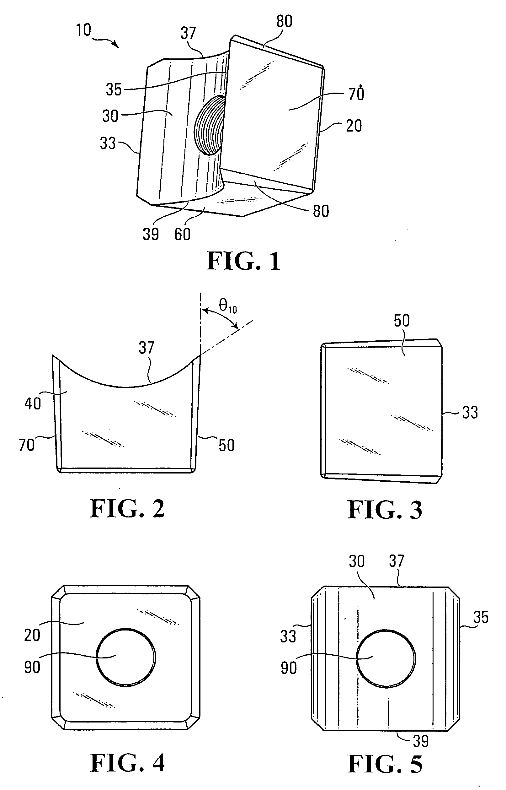
[0036]FIGS. 1 to 5 show a tooth 10 constructed in accordance with the invention. In one application, the tooth 10 can be used with certain equipment, such as a circular saw, to cut and fell trees. In another application, the tooth 10 can be used with certain other equipment, such as a brush mower, to clear and mulch brush and other debris from a path or area.
[0037]The tooth 10 illustrated in these figures is a 2¼″ tooth, but similar teeth of other sizes may be possible. As a result, dimensions provided in the following description may be seen as applying to the tooth 10 and construed as illustrative for similar teeth that may be larger or smaller than the tooth 10.
[0038]The tooth 10 has a mounting end 20, a cutting end 30, four divergent sides 40, 50, 60, 70, a set of beveled edges 80, and a central mounting hole 90 extending therethrough for receiving a component of a fastening system, such as the bolt.
[0039]The body of the tooth 10 is in a frustro-pyramidal shape with the four div...
second embodiment
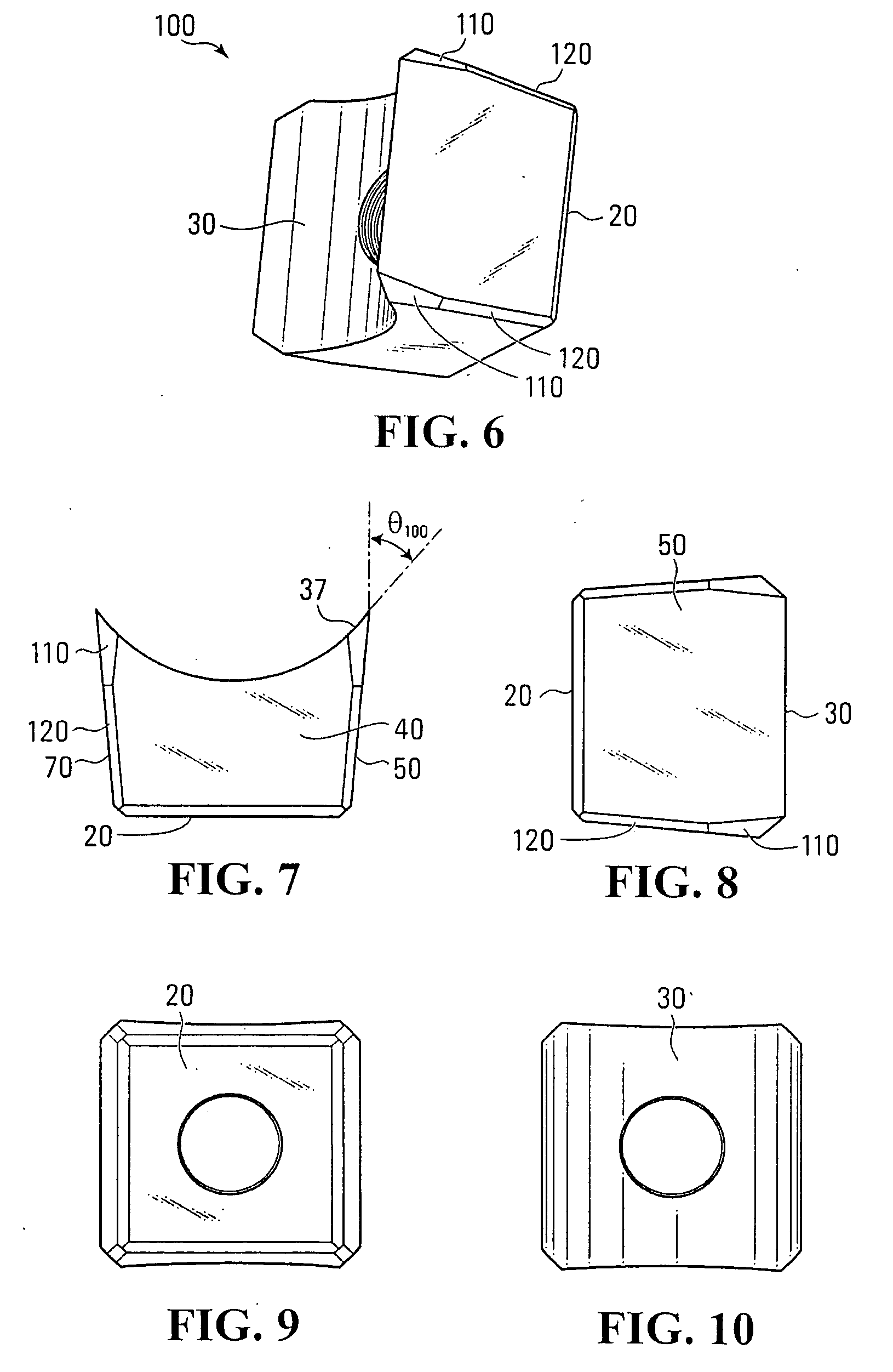
[0049]FIGS. 6 to 10 show a tooth 100 constructed in accordance with the invention.
[0050]In this embodiment, the length of each beveled edge surface comprising the set of bevels 80 includes two portions, namely: (i) a first portion 110 that extends from the cutting end 30 partway towards the mounting end 20 along each edge surface and (ii) a second portion 120 that extends from the end of the first portion 110 to the mounting end 20.
[0051]The first portion 110 of each of the beveled edge surfaces comprising the set of bevels 80 starts from the cutting end 30 and is between 0.6″ and 0.7″ in length, and more preferably is 0.655″ long. The first portion 110 also tapers from an initial width of between 0.25″ and 0.26″ at its widest point (more preferably 0.258″ wide at this point), to a width of between 0.10″ and 0.12″, and more preferably is 0.112″ wide.
[0052]The second portion 120 of each of the beveled edge surfaces comprising the set of bevels 80 starts at the end of the first portio...
fifth embodiment
[0055]FIGS. 11 to 16 show a tooth 200, 300, 400 constructed in accordance with a third, fourth and fifth embodiment of the invention. In these embodiments, an insert 210 of a different material, such as tungsten carbide steel, has been incorporated into the tooth 200, and more specifically, at an angle that orients it somewhat perpendicular to the cutting end 30. The insert 210 becomes part of the cutting surface of the first pair of opposed cutting edges 33, 35, as well as of the cutting surface of the second pair of opposed cutting edges 37, 39. As a result, the cutting surfaces is thus made of the material in the insert 210 (e.g., tungsten carbide steel) rather than of the material of the rest of the body of the tooth 200. This may provide certain advantages to the tooth 200 such as a longer operational life, a cutting edge that better retains its sharpness and / or better resistance to erosion or abrasion, as well as from fractures resulting from contact with materials to be cut.
[...
PUM
| Property | Measurement | Unit |
|---|---|---|
| Angle | aaaaa | aaaaa |
| Angle | aaaaa | aaaaa |
| Angle | aaaaa | aaaaa |
Abstract
Description
Claims
Application Information