
Micro-channel heat exchanger

Inactive Publication Date: 2010-07-22
DANFOSS AS +1
View PDF1 Cites 27 Cited by
  • Summary
  • Abstract
  • Description
  • Claims
  • Application Information

AI Technical Summary

Benefits of technology

[0005]The object of the present invention is to provide a micro-channel heat exchanger, which can effectively prevent the fins around the bend from deformation when the micro-channel heat exchanger is bent along the length of the manifold.
[0008]Said solution forms a crush stress relief space inside the bend by decreasing the width of the fin inside the bend, thereby avoiding the deformation of the fins on the two inner sides adjacent to the bend due to crushing and meanwhile maintaining the ventilation and heat exchange functionalities of the bend.
[0010]Since the gap of the fins of the bend is greater than the gap of the fins on the two sides adjacent to the bend, when being bent, the fins of the bend will be deformed first as being relatively weak supported, thereby effectively preventing the fins around the bend from being deformed; moreover, since the fins of the bend have comparatively great gaps, they still have big space allowing for air passage after being crushed. Thus, the ventilation and heat exchange functionalities of the bend can be maintained.
[0014]The solution forms the required bend by interconnecting the heat exchanger cores via elbow pipes, thereby avoiding directly bending the heat exchanger cores. Therefore, fin deformation caused by the bending of the heat exchanger cores is avoided.

Problems solved by technology

Fins inside the heat exchanger are crushed, deformed and distorted during the bending process, thereby influencing the heat exchange performance of the heat exchanger and making the appearance of the heat exchanger not aesthetically pleasing.
Additionally, the portions of the heat exchanger outside of the bend will be torn where the manifolds are welded to flat tubes, which results in the decrease in the burst pressure of the heat exchanger.

Method used


Image

  • Micro-channel heat exchanger
  • Micro-channel heat exchanger
  • Micro-channel heat exchanger

Examples


Embodiment Construction

[0021]Various embodiments of the micro-channel heat exchanger of the present invention will be described in conjunction with the accompanying drawings. It shall be noted that various embodiments described below are only for illustration of the present invention but not intended to limit the present invention.

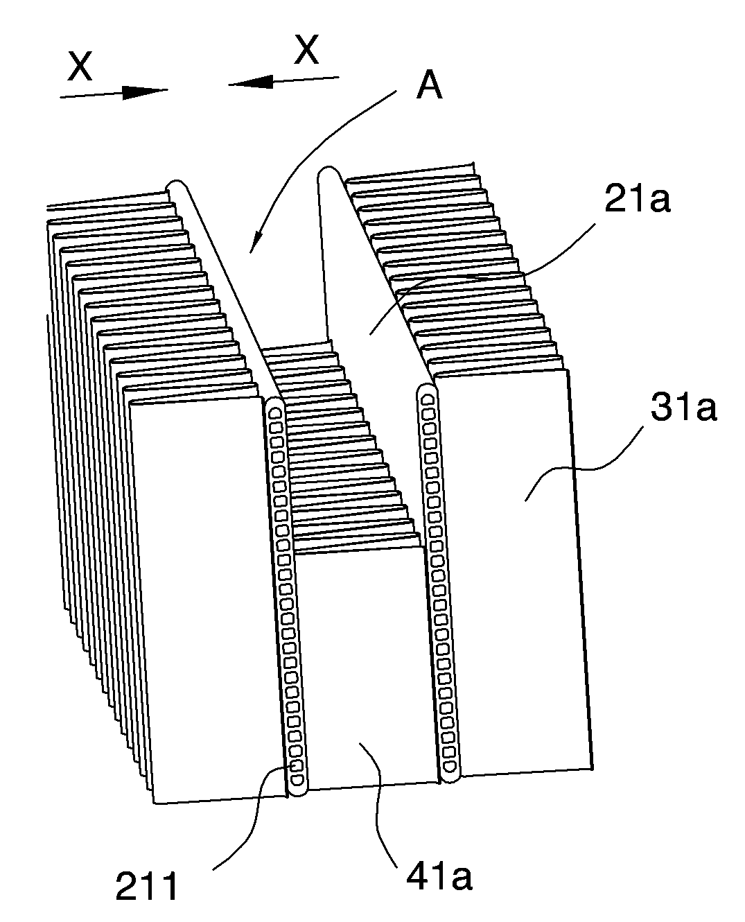
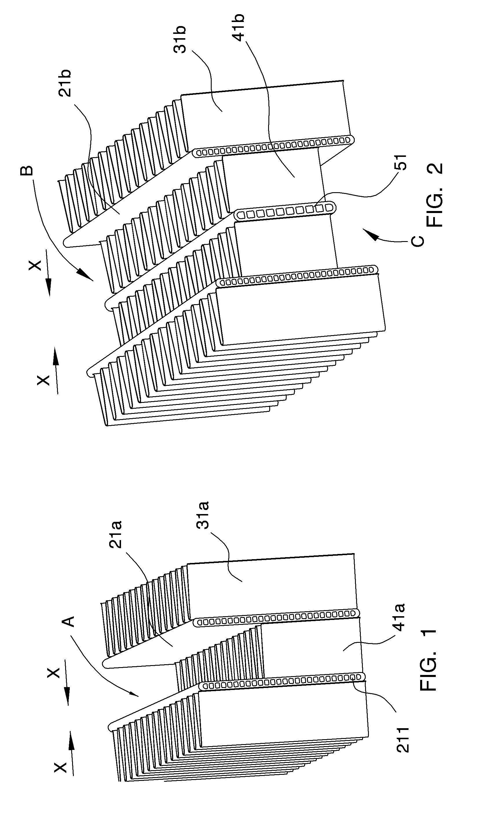
[0022]FIG. 1 is a partial perspective view of a first preferable embodiment of the micro-channel heat exchanger of the present invention. A micro-channel heat exchanger in accordance with the present invention typically comprises an upper manifold 11a, a lower manifold 12a (see FIG. 3), a plurality of micro-channel flat tubes 21a respectively connected to the upper manifold 11a and the lower manifold 12a, and a plurality of rows of fins 31a spaced apart by the micro-channel flat tubes 21a. Both ends of each micro-channel flat tube 21a are respectively inserted into the interiors of the upper manifold 11a and the lower manifold 12a and are fixed with the upper and lower manifolds...


PUM


Abstract

The present invention discloses a micro-channel heat exchanger comprising manifolds, a plurality of micro-channel flat tubes connected to the manifolds, and a plurality of rows of fins spaced apart by the micro-channel flat tubes. The micro-channel heat exchanger is provided with at least one bend designed to avoid the deformation of the fins on two inner sides adjacent to the bend due to crushing and meanwhile maintaining the ventilation and heat exchange functionalities of the bend. For example, the bend may include at least one row of fins where the width of the fins are less than the width of the fins on two sides adjacent to the bend. Alternatively, the gap between the fins in the bend can be greater than the gap between the fins on two sides adjacent to the bend. Still alternatively, the bend can be formed with a space for separating cores of the heat exchanger.

Description

CROSS REFERENCE TO RELATED APPLICATIONS[0001]This application is entitled to the benefit of and incorporates by reference essential subject matter disclosed in Chinese Patent Application No. 200910002435.9 filed on Jan. 20, 2009.TECHNICAL FIELD[0002]The present invention relates to a heat exchanger and more particularly to a micro-channel heat exchanger.BACKGROUND ART[0003]Compared with the conventional heat exchanger, the micro-channel heat exchanger of the present invention has advantages such as higher heat exchange efficiency and less usage of working medium. Since the industry at present places great emphasis and sets higher requirements on environmental protection and energy conservation, the micro-channel heat exchanger has been widely used in many industries owing to its own advantages, for instance, air-conditioning industry, automobile industry and chemical mechanical industry.[0004]Due to particular design requirements or mounting space constraints, the micro-channel heat...

Claims


Application Information

Patent Timeline
IPC IPC(8): F28F9/02
CPCF28D1/05383F28D2001/0266F28F2215/04F28F2260/02F28F1/126
Inventor HUAZHAO, LIUFENG, WANGYUAN, GAOHUANG, LIN-JIE
Owner DANFOSS AS
Features
  • Generate Ideas
  • Intellectual Property
  • Life Sciences
  • Materials
  • Tech Scout
  • Unparalleled Data Quality
  • Higher Quality Content
  • 60% Fewer Hallucinations
Learn More