
Money handling machine

a technology of money handling machine and money, which is applied in the direction of instruments, apparatus for dispensing discrete objects, and de-stacking objects, etc., can solve the problem of insufficient amount of money dispensed, and achieve the effect of quick processing

Active Publication Date: 2010-07-22
GLORY KOGYO KK
View PDF4 Cites 20 Cited by
  • Summary
  • Abstract
  • Description
  • Claims
  • Application Information

AI Technical Summary

Benefits of technology

[0026]With a money handling machine according to the present invention, it is possible to transport money to a dispensing portion through the transport of the money by money transport unit. Since it is provided with a dispensing limitation portion, it is possible to prevent money that is not allowed to be dispensed from being dispensed.
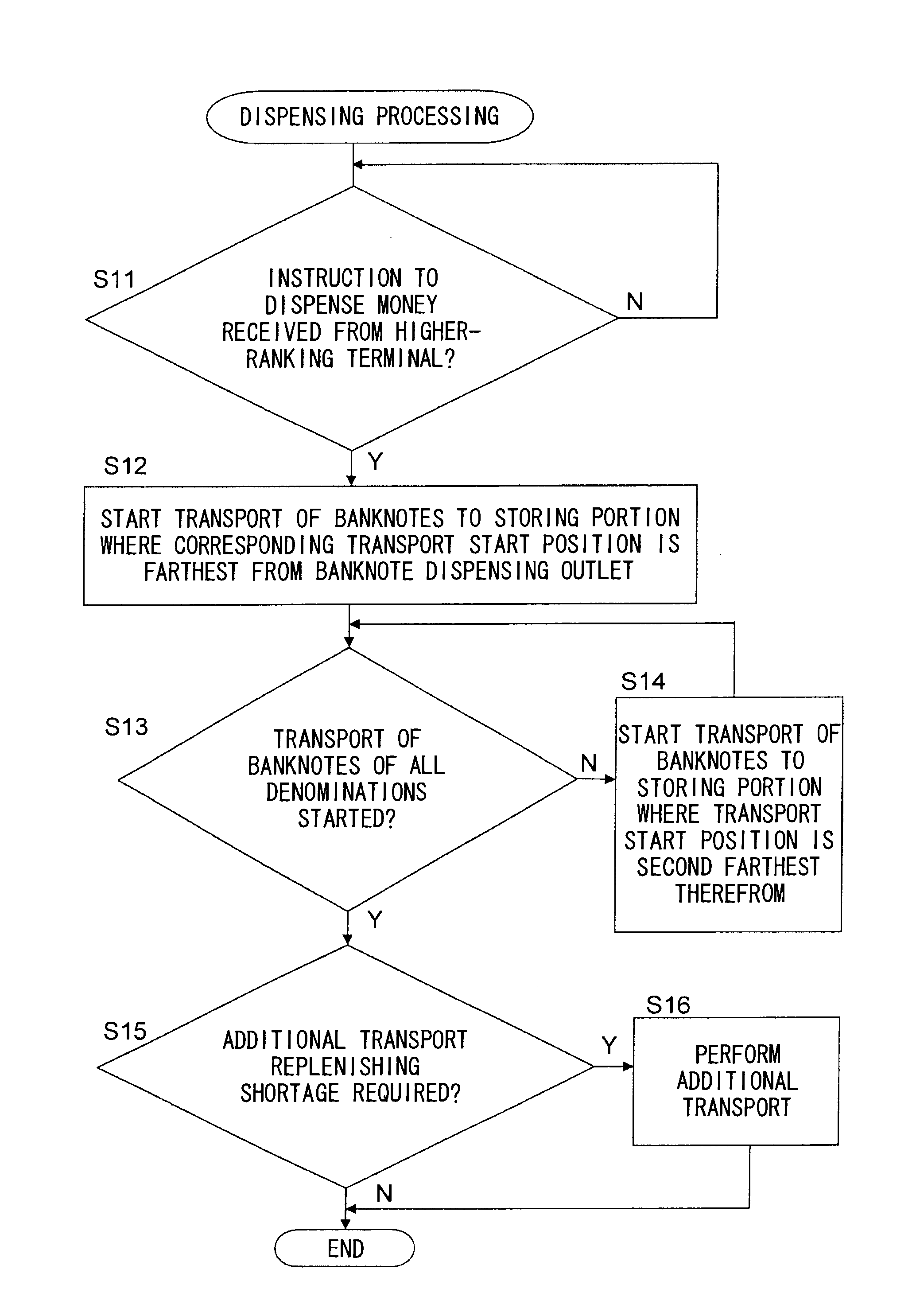
[0027]In the dispensing process, the processing (or a shortage of dispensed money is not replenished until the transport of the amount of all money corresponding to an instruction to dispense money is started) in the first and second steps is performed. Thus, it is possible to quickly perform the processing as compared with dispensing processing in which a shortage of dispensed money is checked each time money of a given denomination is dispensed, and in which the money of the denomination is continuously dispensed (the process does not proceed to the dispensing of another denomination) until the shortage is replenished.

Problems solved by technology

When the dispensing limitation processing described above is performed, the amount of money that reaches the dispensing outlet is reduced by the amount of money that undergoes such processing, and thus, if the reduced amount of money is left without being treated, the amount of money dispensed is insufficient.

Method used


Image

  • Money handling machine
  • Money handling machine
  • Money handling machine

Examples


example 1

[0054]An embodiment of the present invention will be described below with reference to the accompanying drawings. The configuration of a circulation type banknote depositing and dispensing machine (hereinafter referred to as a “banknote depositing and dispensing machine”) according to this embodiment will be first described.

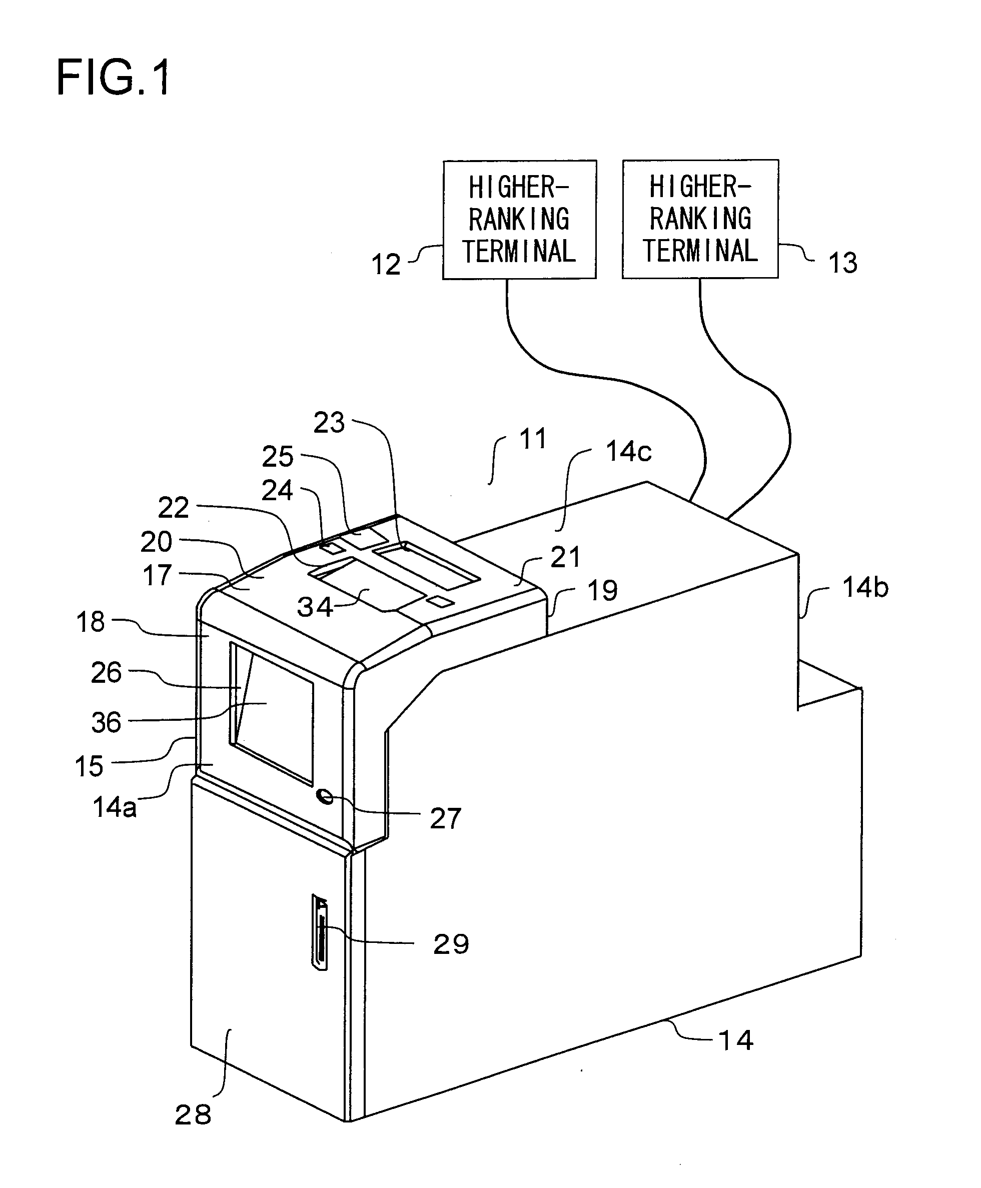
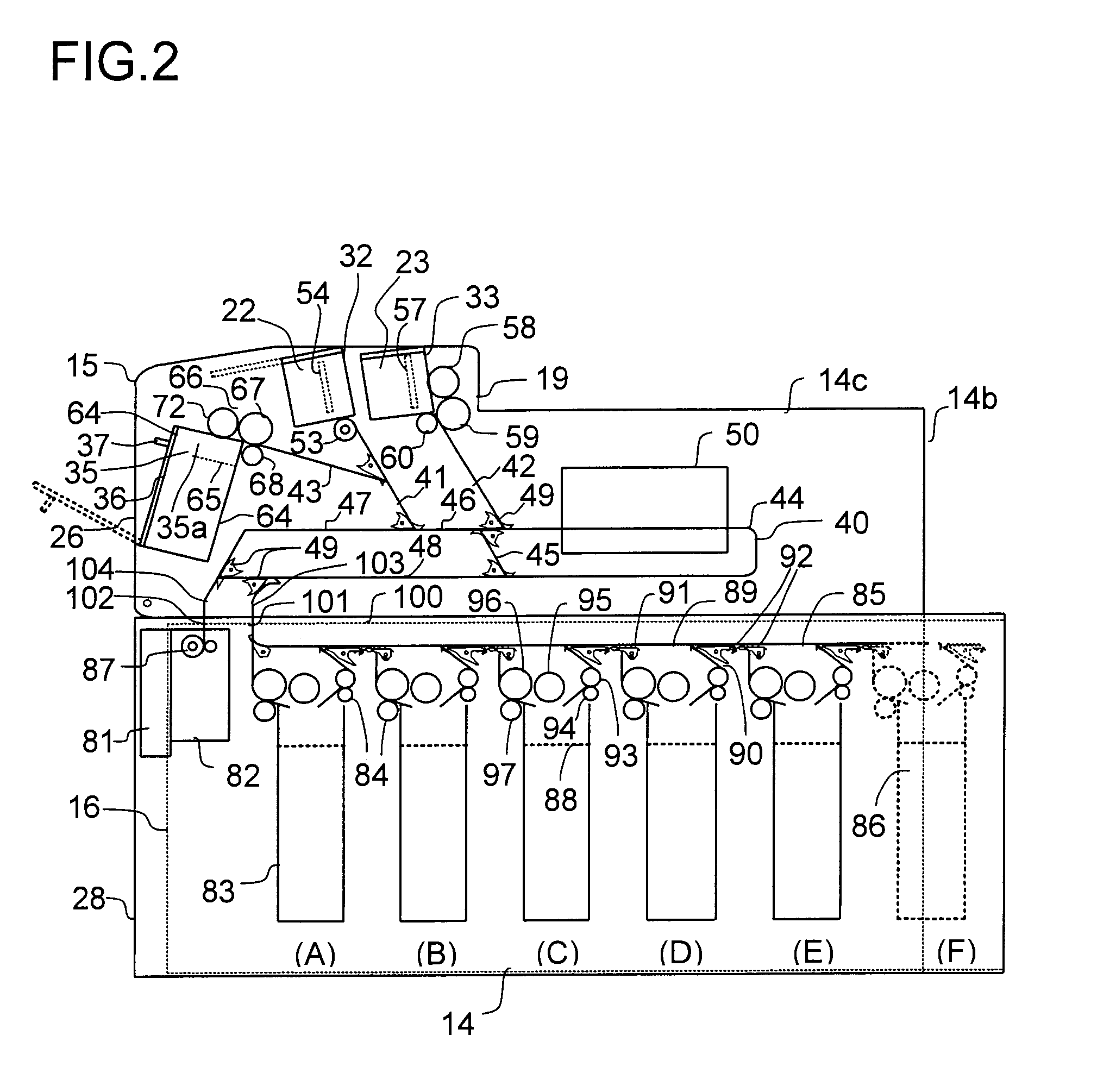
[0055]In FIG. 1, an appearance diagram of the circulation type banknote depositing and dispensing machine (hereinafter simply referred to as the “banknote depositing and dispensing machine”) 11 is shown; in FIG. 2, a cross-sectional view of the banknote depositing and dispensing machine 11 is shown. This banknote depositing and dispensing machine 11 is installed in the counter of a financial institution such as a bank, and specifically is installed between two tellers behind the counter; the depositing and dispensing machine 11 can be used by either or both of the tellers on the left and right of the banknote depositing and dispensing machine 11.

[0056]The banknot...

example 2

[0112]Example 2 will now be described. In the above-described banknote depositing and dispensing machine (money handling machine), a limit capacity is previously determined for each of the denomination-specific banknote storing portions 83 such that banknotes are prevented from being stored beyond the limit capacity. One specific way to realize it is to stop all the depositing processing when the denomination-specific banknote storing portion 83 of a certain denomination reaches the limit capacity.

[0113]In this way, although, when banknotes of a denomination other than the denomination corresponding to the denomination-specific banknote storing portion 83 that reaches the limit capacity are deposited, the banknotes of this denomination can be substantially deposited (in terms of the capacity of the storing portion), until the banknotes stored in the denomination-specific banknote storing portion 83 that reaches the limit capacity are collected halfway (the banknotes are taken out of...

example 3

[0116]Example 3 will now be described. The denomination-specific banknote storing portions 83 and the deposited banknote escrow portion 35 described above are provided with a mechanism (feed-out mechanism) for feeding out banknotes stored temporarily. Here, the operation of a conventional feed-out mechanism will be specifically described below.

[0117]In this feed-out mechanism, feed-out rollers (a feed roller and a kick roller connected thereto) are rotated one revolution, and thus one banknote is fed out. Banknotes are randomly stored on top of each other in a storage space slightly larger than the size of the plane of the banknote. In particular, a device that handles banknotes in which there is a difference between dimensions in their short edge direction may need to be operated with a storage space for banknotes larger than that of a conventional device so that a unit is standardized.

[0118]The first banknote is moved a distance (referred to as a “space movement distance”) compose...


PUM


Abstract

A money handling machine of the present invention includes a denomination-specific storing portion, money transport unit that transports money to a dispending portion and transport starting unit that starts, with the money transport unit, transport of the money stored in the denomination-specific storing portion. The money handling machine receives an instruction to dispense money, performs dispensing money in which the amount of money to be dispensed out of the money stored in the denomination-specific storing portion is only transported to the dispensing portion and performs dispensing limitation processing in which the transport of money determined not to be allowed to be dispensed is prevented from being completed. The dispensing processing includes the first step of starting the transport of the amount of money corresponding to the instruction to dispense money and the second step of transporting, after completion of the first step, money from the denomination-specific storing portion to the dispensing portion such that a shortage of dispensed money produced by performing the dispensing limitation processing is replenished. In this way, it is possible not only to prevent money that is not allowed to be dispensed from being dispensed and to accurately dispense money corresponding to the instruction to dispense money but also to more quickly perform the dispensing processing.

Description

TECHNICAL FIELD[0001]The present invention relates to a money handling machine that performs processing such as for dispensing money such as banknotes.BACKGROUND ART[0002]In the window of a financial institution or the like, a money handling machine is used that is disclosed in, for example, patent document 1 and that performs depositing processing, dispensing processing and other types of processing. In the money handling machine, for example, when dispensing processing is performed, the amount of money corresponding to an instruction to dispense money is selected from money stored in a storing portion and is sequentially placed on a transport line. Such money is transported along the transport line to a predetermined dispensing outlet, with the result that the dispensing processing is achieved.[0003]On the other hand, in the dispensing processing, in consideration of the possibility that money (for example, severely damaged money) which is unsuitable for being dispensed is stored ...

Claims


Application Information

Patent Timeline
Patent Type & Authority Applications(United States)
IPC IPC(8): B65D83/08G06F17/00
CPCG07D11/0054G07D11/0018G07D11/14G07D11/24
Inventor MIZUSHIMA, YOSHIKATSU
Owner GLORY KOGYO KK
Learn More