
Switching power supply controller with selective feedback sampling and waveform approximation

a power supply controller and feedback sampling technology, applied in the direction of dc-dc conversion, climate sustainability, power conversion systems, etc., can solve the problems of parasitic resistance rsub>p /sub> between these nodes, power supply controllers with on-chip switches,

Active Publication Date: 2010-07-22
ANALOG DEVICES INC
View PDF10 Cites 52 Cited by
  • Summary
  • Abstract
  • Description
  • Claims
  • Application Information

AI Technical Summary

Benefits of technology

[0010]The present switching power supply controller is adapted to be connected to external components to produce a regulated output voltage at an output node. The controller requires at least one switching element, and is arranged to control a switching cycle during which the switching elements are switched on and off to regulate the output voltage. The controller has a feedback signal which represents the output voltage produced at the output node, and a circuit node—such as a chip ground node—which conducts a current that is higher during a second portion of the switching cycle than it is during a first portion of the switching cycle, such that the feedback signal varies with the current conducted by the circuit node.

Problems solved by technology

However, a problem can arise with a switching power supply controller IC having on-chip switches, such as that shown in FIG. 1.
However, in practice, a parasitic resistance RP is present between these nodes.
When switch current isw flows through RP, a voltage drop is developed across RP which can reduce the accuracy of feedback signal Vfbd.
Thus, there is an error in the feedback signal only during certain portions of the switching cycle.
Moreover, the parasitic resistance between the external ground node and the chip ground node is generally beyond the direct control of the controller designer, and so the magnitude of the resulting voltage drop is unknown.
This approach, however, requires additional pins which are too costly for many applications.
This approach, however, requires knowledge of the parasitic resistance value, which as mentioned above, is generally beyond the control of the designer.

Method used


Image

  • Switching power supply controller with selective feedback sampling and waveform approximation
  • Switching power supply controller with selective feedback sampling and waveform approximation
  • Switching power supply controller with selective feedback sampling and waveform approximation

Examples


Embodiment Construction

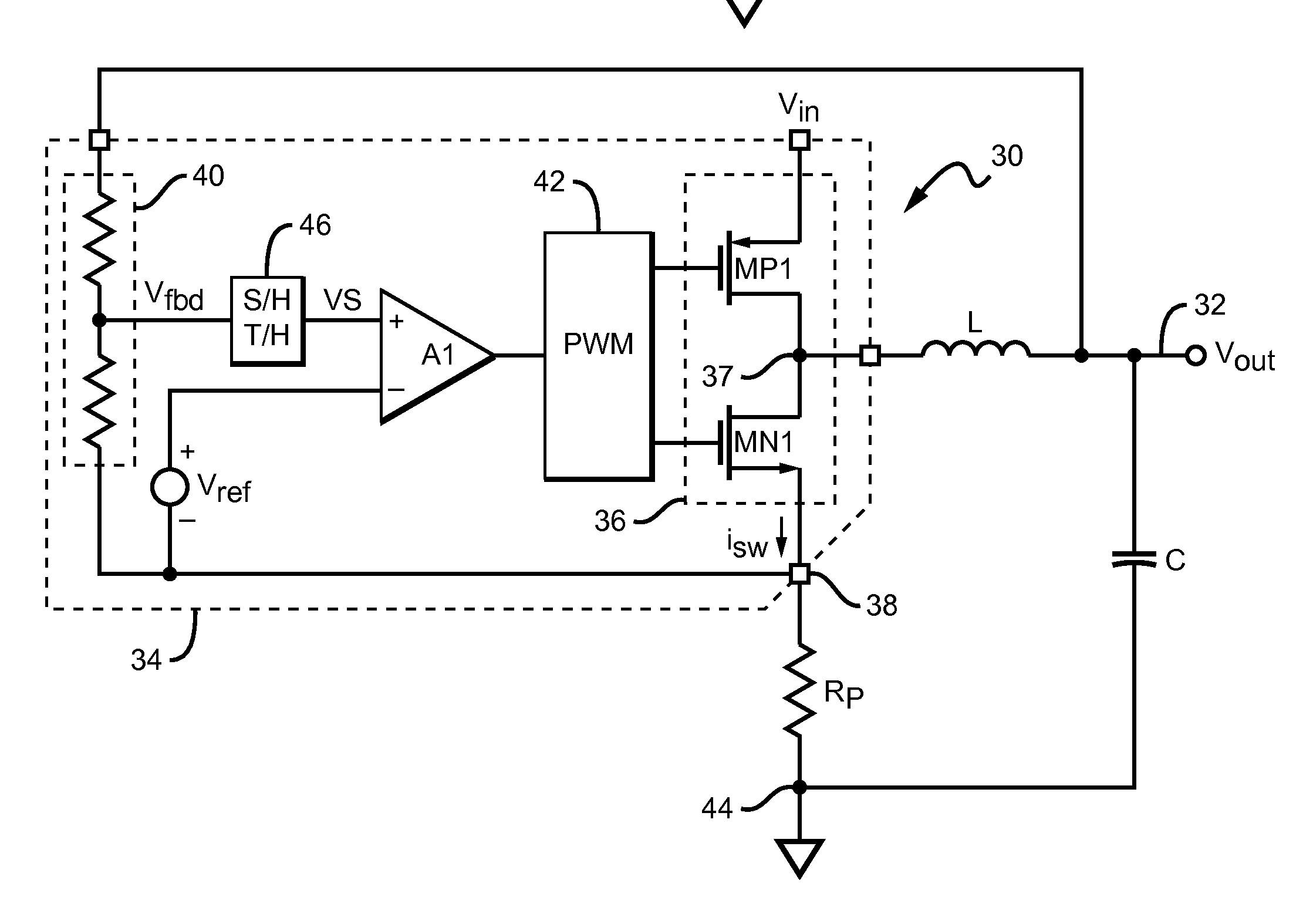
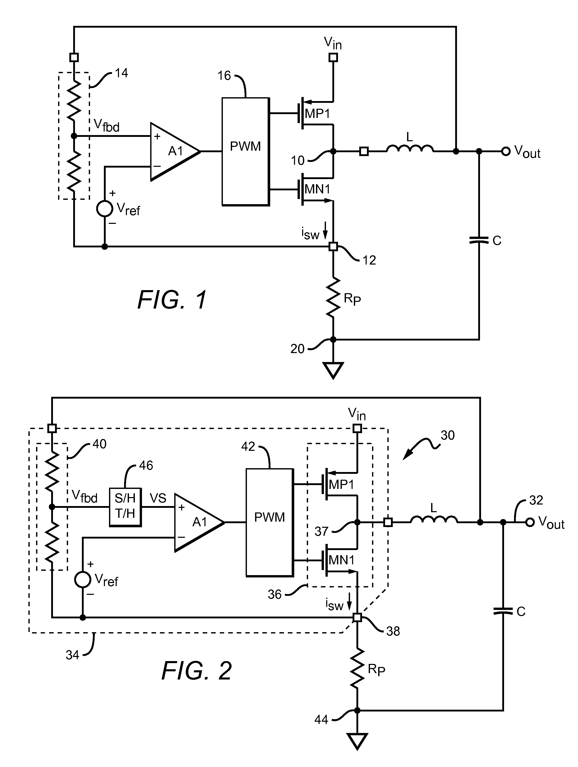
[0026]A switching power supply controller in accordance with the present invention is shown in FIG. 2. The controller 30 is adapted to be connected to external components to produce a regulated output voltage Vout at an output node 32. In the exemplary embodiment shown in FIG. 2, the controller components are fabricated on a common IC die 34, which is connected to external components such as an output inductor L and output capacitor C. It should be understood that a practical switching power supply is likely to include additional components which, for clarity, have not been shown in FIG. 2.

[0027]The controller requires at least one switching element 36, and is arranged to control a switching cycle during which the switching elements are switched on and off to regulate output voltage Vout. In the embodiment shown, switching element 36 comprises a PMOS FET MP1 and an NMOS FET MN1 which are connected together at a switching node 37; however, other switching element types and configurat...


PUM


Abstract

A switching power supply controller which includes at least one switching element, and controls a switching cycle during which the switching elements are switched on and off to regulate the power supply's output voltage. The controller has a feedback signal which represents the output voltage, and a circuit node which conducts a current that is higher during a second portion of the switching cycle than it is during a first portion, such that the feedback signal varies with the current conducted by the node. To overcome feedback signal inaccuracies, a sampling circuit samples a signal which varies with the feedback signal only during the first portion of the switching cycle; the controller then regulates the output voltage in response to the sampled signal. The sampling circuit may be further arranged to produce an output which approximates the portion of the feedback signal waveform which is not sampled.

Description

RELATED APPLICATIONS[0001]This application claims the benefit of provisional patent application No. 61 / 205,446 to Kenneth Richardson, filed Jan. 21, 2009.BACKGROUND OF THE INVENTION[0002]1. Field of the Invention[0003]This invention relates to switching power supply controllers.[0004]2. Description of the Related Art[0005]Switching power supply controllers are typically fabricated as an integrated circuit (IC), which is connected to external components such as an output inductor and capacitor to form a complete switching power supply. A switching power supply requires one or more switching elements, which can be on- or off-chip.[0006]A typical switching power supply configuration is shown in FIG. 1. The on-chip components include a switching transistor MP1 connected between an input voltage Vin and a switching node 10, and a switching transistor MN1 connected between switching node 10 and an internal chip ground node 12. An error amplifier A1 receives a feedback signal Vfbd which va...

Claims


Application Information

Patent Timeline
Patent Type & Authority Applications(United States)
IPC IPC(8): G05F1/10
CPCY02B70/1466H02M3/1588Y02B70/10
Inventor RICHARDSON, KENNETH G.
Owner ANALOG DEVICES INC
Features
  • Generate Ideas
  • Intellectual Property
  • Life Sciences
  • Materials
  • Tech Scout
  • Unparalleled Data Quality
  • Higher Quality Content
  • 60% Fewer Hallucinations
Learn More