
Control of appliances, kitchen and home

a technology for appliances and kitchens, applied in the field of appliances, can solve problems such as difficult use of appliances, and achieve the effect of easing kitchen and house work

Inactive Publication Date: 2010-07-22
PRYOR TIMOTHY
View PDF99 Cites 218 Cited by
  • Summary
  • Abstract
  • Description
  • Claims
  • Application Information

AI Technical Summary

Benefits of technology

[0008]The invention is related to several of my co-pending applications and previous patents which describe a new form of RTD control surface aimed at answering the needs above, and in providing a plethora of new added features which can ease kitchen and house work, while allowing the user to share time for home functions with internet shopping, social networking and the like.

Problems solved by technology

In some cases, features which companies have added to differentiate their products, have actually made the appliance more difficult to use.

Method used


Image

  • Control of appliances, kitchen and home
  • Control of appliances, kitchen and home
  • Control of appliances, kitchen and home

Examples


Embodiment Construction

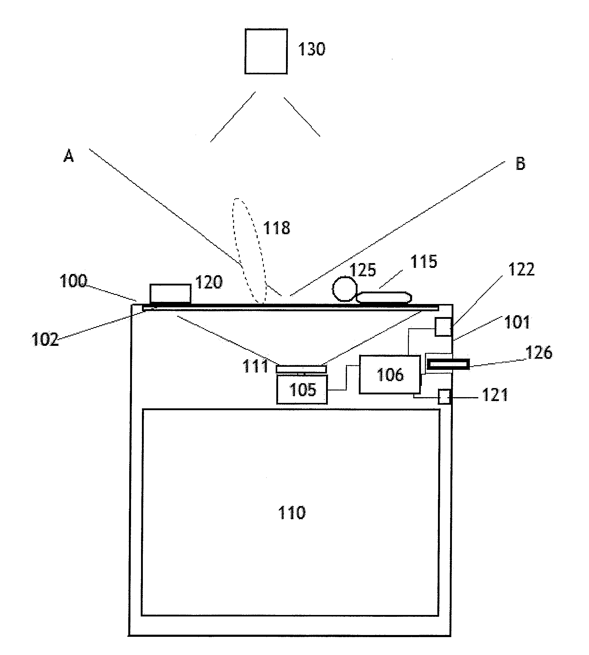
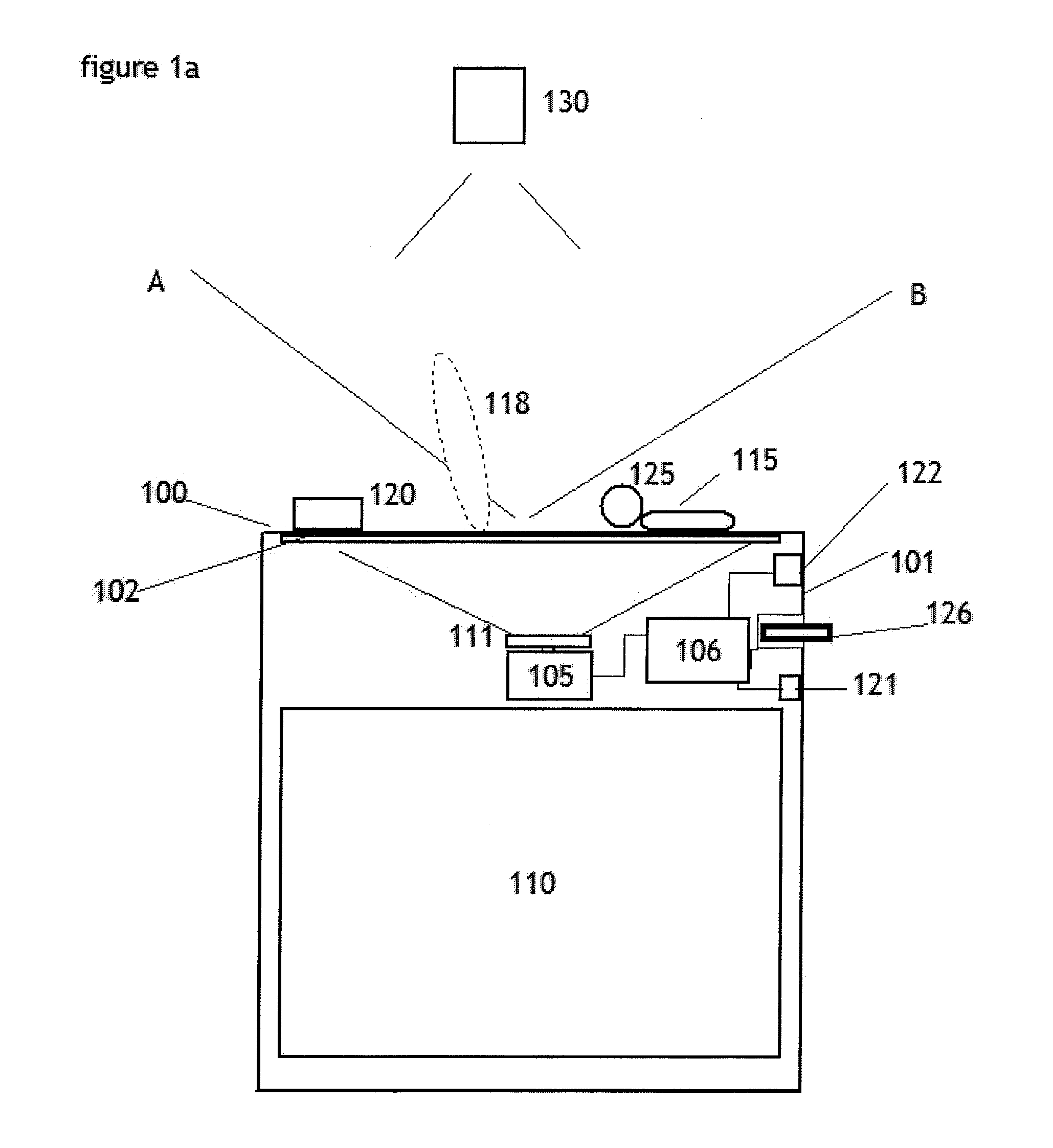
[0071]FIG. 1a illustrates an island located counter top embodiment of the invention, including a washable work-board and display surface, in which persons hands or fingers, or work objects placed on the surface are electro-optically sensed, in addition to sensing. Also illustrated is the sensing of physical control details such as knobs and switches which may also be desired for control or other purposes.

[0072]FIG. 1a herein in side view illustrates a kitchen counter of the invention 100, in this case in an island of the kitchen 101 having unique abilities to aid food preparation. The invention uses the RTD device shown in many of my co pending applications and patents and uses a TV camera or other electro-optical sensor and projector combination 105 (controlled by computer 106) to project onto a screen such as 102 forming a portion of the counter, and to sense, for example a persons hands or fingers or work objects or food or other materials on the screen surface 102, which also ma...


PUM


Abstract

The disclosed invention is generally in the field of control of appliances in the home, and in their networking and connectivity also with audio systems and internet sources and the integration of these elements in a connected manner. Preferred apparatus generally employs a video projection system and one or more TV cameras. Embodiments of the invention may be used to enhance the social interaction and enjoyment of persons in the kitchen and reduce the work of food preparation. The invention may be used in many rooms of the house, and contribute to the well being of seniors and others living therein.

Description

[0001]This application is a continuation of U.S. patent application Ser. No. 12 / 468,401, filed May 19, 2009 (now U.S. Pat. No. ______), which claims the benefit of U.S. Provisional Application No. 61 / 054,643, filed May 20, 2008, and which is a continuation-in-part of U.S. patent application Ser. No. 12 / 358,404 (now U.S. Pat. No. ______), filed Jan. 23, 2009, U.S. patent application Ser. No. 11 / 980,722 (now U.S. Pat. No. ______), filed Oct. 31, 2007, U.S. patent application Ser. No. 11 / 980,721 (now U.S. Pat. No. ______), filed Oct. 31, 2007, U.S. patent application Ser. No. 11 / 980,710 (now U.S. Pat. No. ______), filed Oct. 31, 2007, U.S. patent application Ser. No. 11 / 832,134 (now U.S. Pat. No. ______), filed Aug. 1, 2007, U.S. patent application Ser. No. 11 / 272,868 (now U.S. Pat. No. ______), filed Nov. 15, 2005, U.S. patent application Ser. No. 11 / 045,131 (now U.S. Pat. No. ______), filed Jan. 31, 2005, and U.S. patent application Ser. No. 10 / 934,762 (now U.S. Pat. No. ______), fil...

Claims


Application Information

Patent Timeline
IPC IPC(8): B60Q1/00G06F3/042G06F3/0488
CPCG01F23/292G05B19/0423G05B2219/23031G05B2219/2643G05B2219/31048G06F3/017G06F3/0425F24C7/082H05B6/6435H05B2213/04A47L15/0063F24C15/2021G06F3/0304G06F3/0346
Inventor PRYOR, TIMOTHY
Owner PRYOR TIMOTHY
Learn More