
Ink jet head and ink supplying method thereof

a technology of ink jet head and ink supply method, which is applied in the direction of printing, other printing apparatus, etc., can solve the problems of increased manufacturing cost, abnormal discharge, and large manufacturing equipment for photolithography process

Active Publication Date: 2010-07-22
SAMSUNG DISPLAY CO LTD
View PDF4 Cites 35 Cited by
  • Summary
  • Abstract
  • Description
  • Claims
  • Application Information

AI Technical Summary

Benefits of technology

[0010]The present invention prevents the generation of vapor on the head unit of an inkjet head which is part of an inkjet printing system, in order to prevent abnormal discharge of the nozzle due to the vapor.
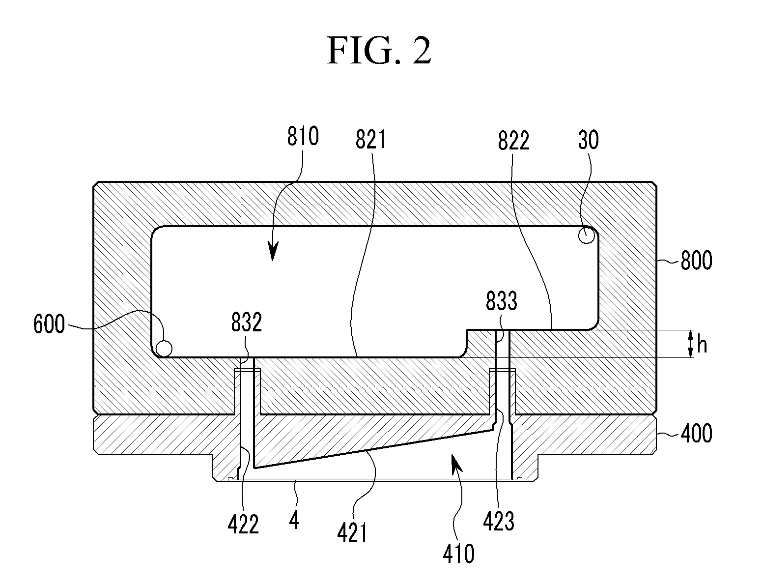
[0024]According to an exemplary embodiment of the present invention, the floors of the inner storage space of the ink storage unit have a step such that the ceiling of the inner flow space of the head unit is inclined, thereby preventing the vapor from being confined by the head unit. Accordingly, the ink including the vapor is not discharged through the nozzle, thereby preventing the discharge deterioration. Furthermore, the lower injection hole and the upper injection hole are formed asymmetrically in the structure, so that the ink flows in a predetermined direction.
[0025]Also, when supplying the ink, a discharge unit guiding the ink in a predetermined direction and a valve controlling the discharge unit to remove the vapor are not required such that the structure is simple, and a driving unit and a controller for shutting off the valve are not necessary, thereby being economical.
[0026]Also, when supplying the ink, a non-uniformity of the discharge amount according to the position of the nozzles, which may be easily generated in the structure where the injection holes are formed asymmetrically for the ink to flow in a predetermined direction, may be prevented, as will be shown further below.

Problems solved by technology

Moreover, much larger manufacturing equipment for a photolithography process may also be needed.
This usually results in increased manufacturing costs.
This vapor closes the flow path of the nozzles while flowing, such that abnormal discharge may be generated.
However, a valve is necessary in this case, and as a controller and a device to shut off the valve are required, a large quantity of ink is consumed.
Also, the injection hole is positioned on one side of the ink storage unit, such that the flow resistance is changed according to the position of the nozzle, resulting in a non-uniform discharge amount.

Method used

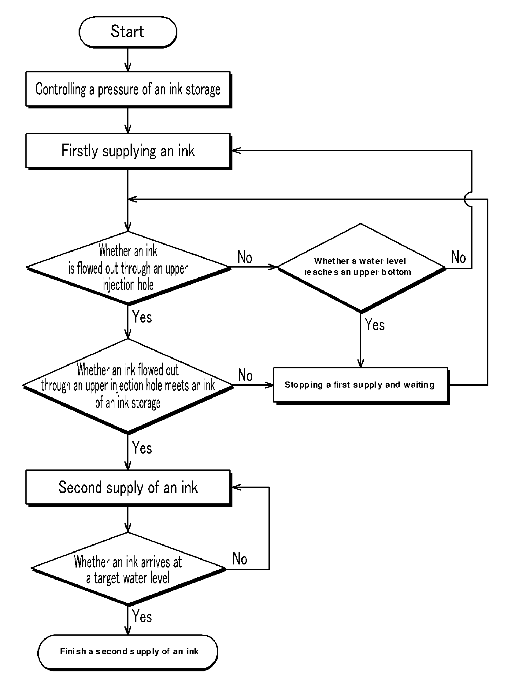

Image

  • Ink jet head and ink supplying method thereof
  • Ink jet head and ink supplying method thereof
  • Ink jet head and ink supplying method thereof

Examples


Embodiment Construction

[0037]The present invention will be described more fully hereinafter with reference to the accompanying drawings, in which exemplary embodiments of the invention are shown. As those skilled in the art would realize, the described embodiments may be modified in various different ways, all without departing from the spirit or scope of the present invention.

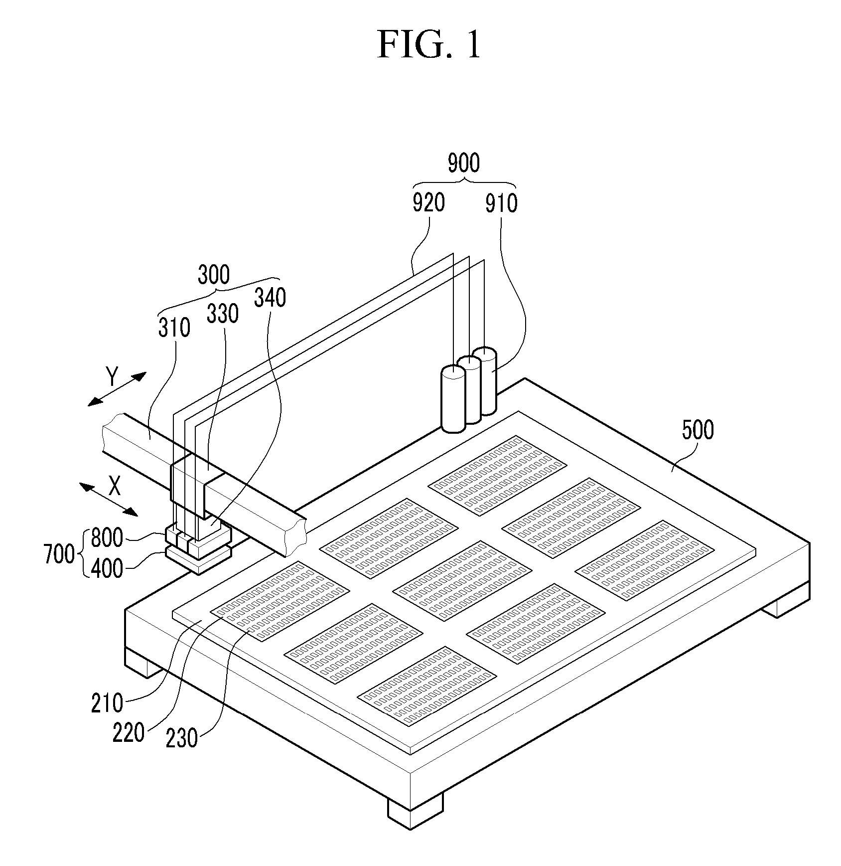
[0038]FIG. 1 is a perspective view of an inkjet printing system including an Inkjet head according to an exemplary embodiment of the present invention, and FIG. 2 is a cross-sectional view of the Inkjet head shown in FIG. 1.

[0039]As shown in FIG. 1, an inkjet printing system including an Inkjet head according to an exemplary embodiment of the present invention includes an Inkjet head 700 dripping ink 231 (see FIG. 4) on a substrate 210, a transfer unit 300 transferring the Inkjet head 700, and a supplying unit 900 supplying the ink 231 to the Inkjet head 700.

[0040]The Inkjet head 700 is disposed and spaced apart from a stage 500 on ...


PUM


Abstract

An Inkjet head according to an exemplary embodiment of the present invention includes an ink storage unit including an inner storage space, a head unit connected to the ink storage unit, and a plurality of nozzles discharging the ink, wherein the floors of the inner storage space of the ink storage unit form a step. Accordingly, in the Inkjet head of an exemplary embodiment of the present invention, the floors of the inner storage space of the ink storage unit form a step, and the ceiling of the inner flow space of the head unit is inclined, thereby preventing the ink vapor from being confined inside the head unit. Therefore, the ink to be discharged through the nozzle flows in a predetermined direction and does not include ink vapor, thereby preventing discharge deterioration.

Description

CROSS-REFERENCE TO RELATED APPLICATION[0001]This application claims priority to and the benefit of Korean Patent Application No. 10-2009-0004677 filed in the Korean Intellectual Property Office on Jan. 20, 2009, the entire contents of which are incorporated herein by reference.BACKGROUND OF THE INVENTION[0002](a) Field of the Invention[0003]The present invention relates to an Inkjet head and an ink supplying method.[0004](b) Description of the Related Art[0005]Generally, various thin film patterns of flat panel displays such as a liquid crystal display (LCD) and an organic light emitting diode (OLED) display are formed through a photolithography process. A large flat panel display uses more materials during manufacturing, such as a photosensitive film that is applied on a substrate to form a thin film pattern. Moreover, much larger manufacturing equipment for a photolithography process may also be needed. This usually results in increased manufacturing costs.[0006]In order to minimi...

Claims


Application Information

Patent Timeline
IPC IPC(8): B41J29/38B41J2/175
CPCB41J2/175B41J2/17513
Inventor KIM, SUNG-WOOKSHIN, SEUNG-JOOBACK, SEOK-SOON
Owner SAMSUNG DISPLAY CO LTD
Learn More