Multistage transmission

Inactive Publication Date: 2010-07-22
JATCO LTD
View PDF6 Cites 3 Cited by
  • Summary
  • Abstract
  • Description
  • Claims
  • Application Information

AI Technical Summary

Benefits of technology

[0007]It is, therefore, in view of the previously-described disadvantages of the prior art, an object of the invention to provide a multistage transmission configured to enable (i) a clutch function, by which switching between a torque-transmission enabling state and a torque-transmission disabling state occurs, as well as (ii) a shifting function having a higher degree of freedom of speed ratios (i.e., a wide range of speed ratios including a speed-increase ratio (an overdrive mode and / or a super-overdrive mode) as well as a speed-reduction ratio), while achieving reduced or suppressed manufacturing costs and a more compact and light-weight friction-disk-drive construction, and also configured to reduce a spin loss in transmitted torque at a torque-transmission contacting portion corresponding to each of finite shift stages (finite transmission ratios).

Problems solved by technology

Hence, this leads to a very complicated linkage design, increased number of component parts, and increased weight of the three stacks of cone disks, each of which cone disks is tapered so that the thickness decreases from the root to the tip.
The disadvantages of the “Beier” power transmission as disclosed in JU3-2954 are the increased manufacturing costs, the difficulty of reducing the number of component parts constructing the multiple disk drive, and the difficulty of achieving the compactness in the multiple disk drive.
Such a relative-velocity difference leads to the problem of undesired galling contact, thus causing an increased spin loss in transmitted torque.

Method used


Image

  • Multistage transmission
  • Multistage transmission
  • Multistage transmission

Examples


Embodiment Construction

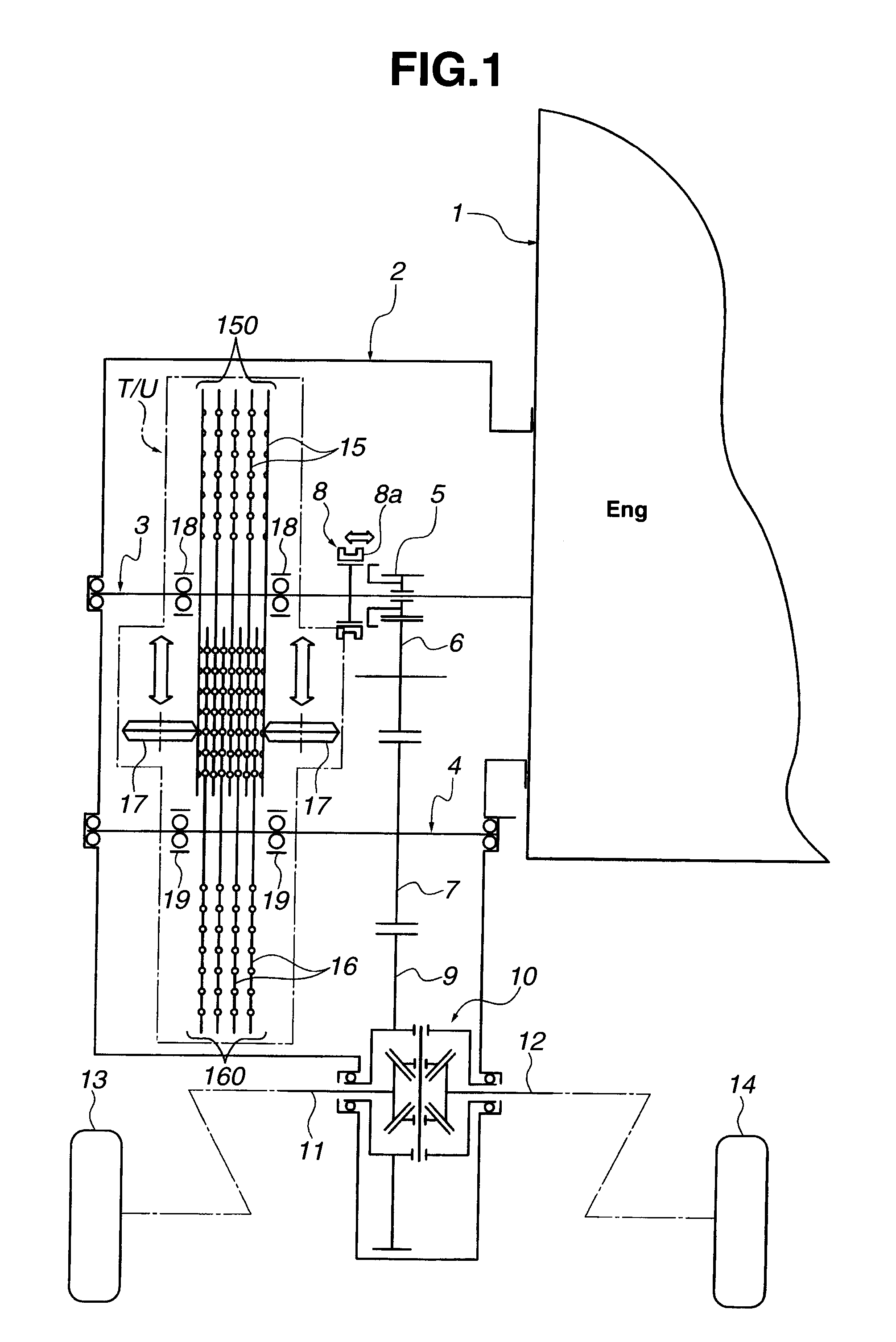
[0026]Referring now to the drawings, particularly to FIG. 1, a multi-disk type multistage transmission unit T / U of the embodiment is exemplified in an automatic transmission system of an automotive vehicle.

[0027]As shown in FIG. 1, in addition to multi-disk type multistage transmission unit T / U of the embodiment, the automotive automatic transmission system also includes an engine 1 (a prime mover), a transmission case 2, an input shaft 3, an output shaft 4, a reverse gear 5, a reverse idler gear 6, an output gear 7, a synchronizing device 8, a final gear 9, a differential unit 10, left and right axle driveshafts 11, 12, and left and right drive road wheels 13, 14.

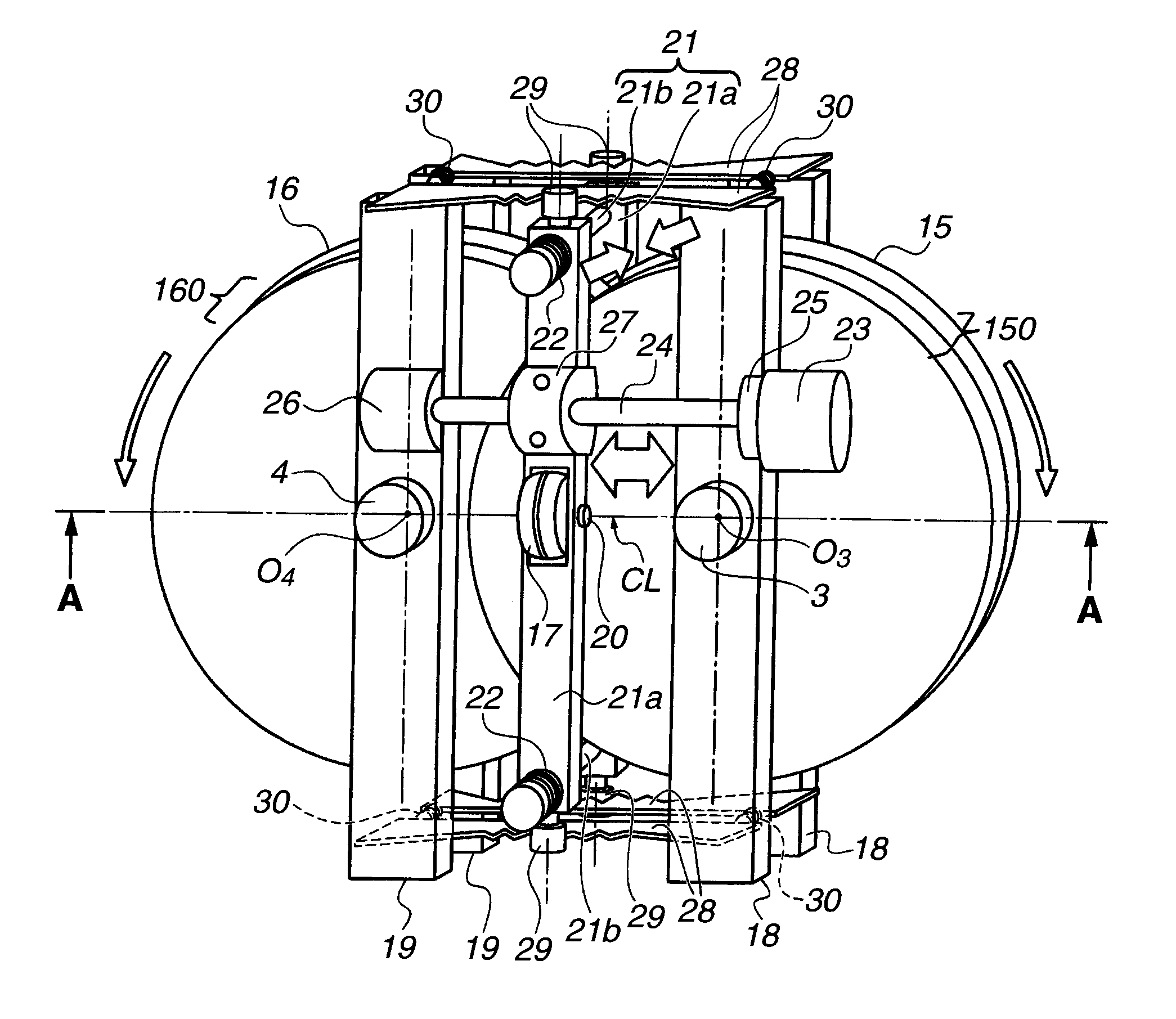
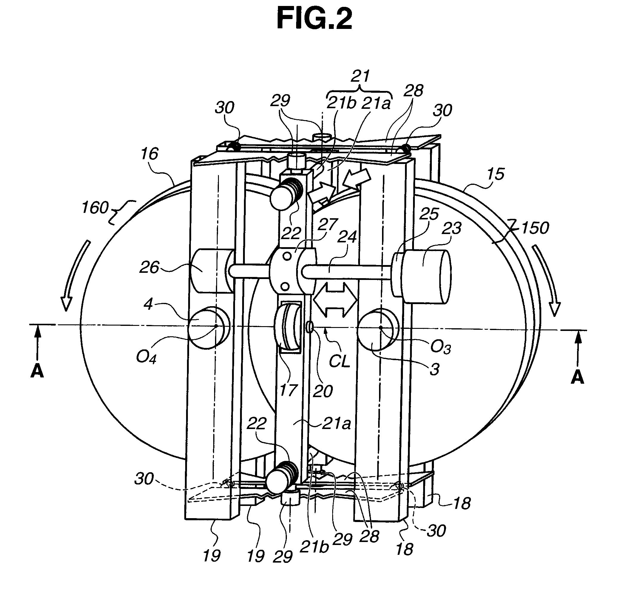
[0028]The previously-noted multi-disk type multistage transmission unit T / U is comprised of a primary disk stack 150, a secondary disk stack 160, a pair of pressure rollers 17, 17 (serving as a pair of pressure-application devices or pressure-application means), a pair of input-shaft support frames 18, 18, and a pair of ou...


PUM


Abstract

In a multistage transmission, a pair of pressure rollers is provided to be movable along a two-axes connecting line of input and output shafts within a disk overlapping area of input and output disks, and configured to sandwich the input and output disks while applying contact pressure from the outside disk faces at a position corresponding to a required transmission ratio. A plurality of ridged portions, formed on each of the input and output disks, are configured such that the entire length of the two-axes connecting line is divided into an input-side driving radius and an output-side driving radius, both determined based on the required transmission ratio, and that an apex of a selected input-side ridged portion and an apex of a selected output-side ridged portion, both determined based on the required transmission ratio, are arranged to oppose each other on the two-axes connecting line.

Description

TECHNICAL FIELD[0001]The present invention relates to a multistage transmission, which can be applied to automotive vehicles, and specifically to a multistage transmission employing a friction-gearing mechanism in which power is transmitted from thin input disks to thin output disks by bringing power-transmission portions of the input and output disks into contact with each other, utilizing elastic deformation of the disks under pressure.BACKGROUND ART[0002]As a transmission with a friction-gearing mechanism, a so-called “Beier” power transmission (or a so-called “Beier” variator) employing a mechanical drive, which drive includes a plurality of cone disks (input disks) and a plurality of flange disks (output disks), is generally known. One such “Beier” power transmission has been disclosed in FIGS. 3-4 in Japanese published Utility Model application No. 3-2954 (hereinafter referred to as “JU3-2954”).[0003]In the “Beier” power transmission as disclosed in JU3-2954, power, inputted i...

Claims


Application Information

Patent Timeline
IPC IPC(8): F16H15/04
CPCF16H15/46F16H15/14
Inventor TANGE, HIROSHI
Owner JATCO LTD
Why Eureka
Try Eureka