
Fuel Delivery Unit With A Filling Level Sensor Operating With Ultrasonic Waves

Inactive Publication Date: 2010-07-29
CONTINENTAL AUTOMOTIVE GMBH
View PDF7 Cites 3 Cited by
  • Summary
  • Abstract
  • Description
  • Claims
  • Application Information

AI Technical Summary

Benefits of technology

[0007]The invention is based on creating a fuel delivery unit that enables a precise determination of the filling level in a fuel tank, with wave guidance being enabled over the entire running path in particular in the case of ultrasound being used. Furthermore, the fuel delivery unit is of a simple design.
[0009]As a result of the receptacle for the support element being formed as far as the base of the swirl pot and the transmitting and receiving unit for ultrasound being arranged such that the ultrasound waves run in the receptacle and in the support element, the receptacle and support element serve as a measuring tube. A separate measuring tube may therefore be dispensed with. As a result of the saving of the separate measuring tube, the fuel delivery unit according to one embodiment of the invention can be produced cost-effectively. The design of the components of receptacle and support element in the form of a telescopic arrangement furthermore ensures that a measuring tube is created which, independently of production tolerances and filling-level-dependent spacings between the base and upper boundary wall of the fuel tank, ensures a guided propagation of the ultrasound waves over the entire height. This is made possible by the support element, as a result of its connection to the flange, extends into the direct vicinity of the upper boundary wall.
[0010]In one advantageous refinement, the transmitting and receiving unit is arranged in the region of the upper end of the support element in the installed position of the fuel delivery unit, as a result of which the transmitting and receiving unit is arranged close to the flange of the fuel delivery unit. This refinement firstly enables the transmitting and receiving unit to be pre-assembled, with the support element. Secondly, on account of the arrangement close to the flange, the electrical connecting lines can be relatively short and therefore less susceptible to failure.
[0012]In a further advantageous refinement, the transmitting and receiving unit is arranged in the lower region, preferably on the base of the receptacle, of the support element in the installed position of the fuel delivery unit. With this arrangement, the measurement takes place through the fuel. As a result, the transmitting and receiving unit can be operated with a relatively low level of power.
[0013]The arrangement of the transmitting and receiving unit with the flange or the swirl pot is realized in a particularly reliable manner by a cohesive connection, preferably by extrusion coating, welding or adhesive bonding. In particular, extrusion coating has the advantage that the transmitting and receiving unit is thereby reliably protected from fuel and its aggressive constituents, with those regions of the transmitting and receiving unit which transmit and receive the ultrasound waves being excluded from the extrusion coating.

Problems solved by technology

Lack of a base reference would lead to an erroneous filling level measurement, since the base of the fuel tank bends as a function of the weight of the fuel, as a result of which the spacing between the base and the upper boundary wall of the fuel tank is dependent on the filling level in the fuel tank.
Therefore, both a filling-level-dependent change in the spacing between the base and the upper boundary wall of the fuel tank and also production-related tolerances in the range of several millimeters have the result that the measuring tube cannot be arranged optimally up to directly below the upper boundary wall of the fuel tank.

Method used


Image

  • Fuel Delivery Unit With A Filling Level Sensor Operating With Ultrasonic Waves
  • Fuel Delivery Unit With A Filling Level Sensor Operating With Ultrasonic Waves
  • Fuel Delivery Unit With A Filling Level Sensor Operating With Ultrasonic Waves

Examples


Embodiment Construction

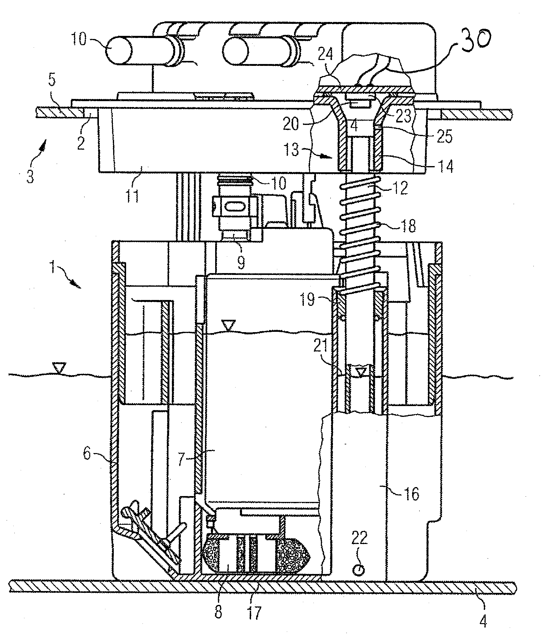
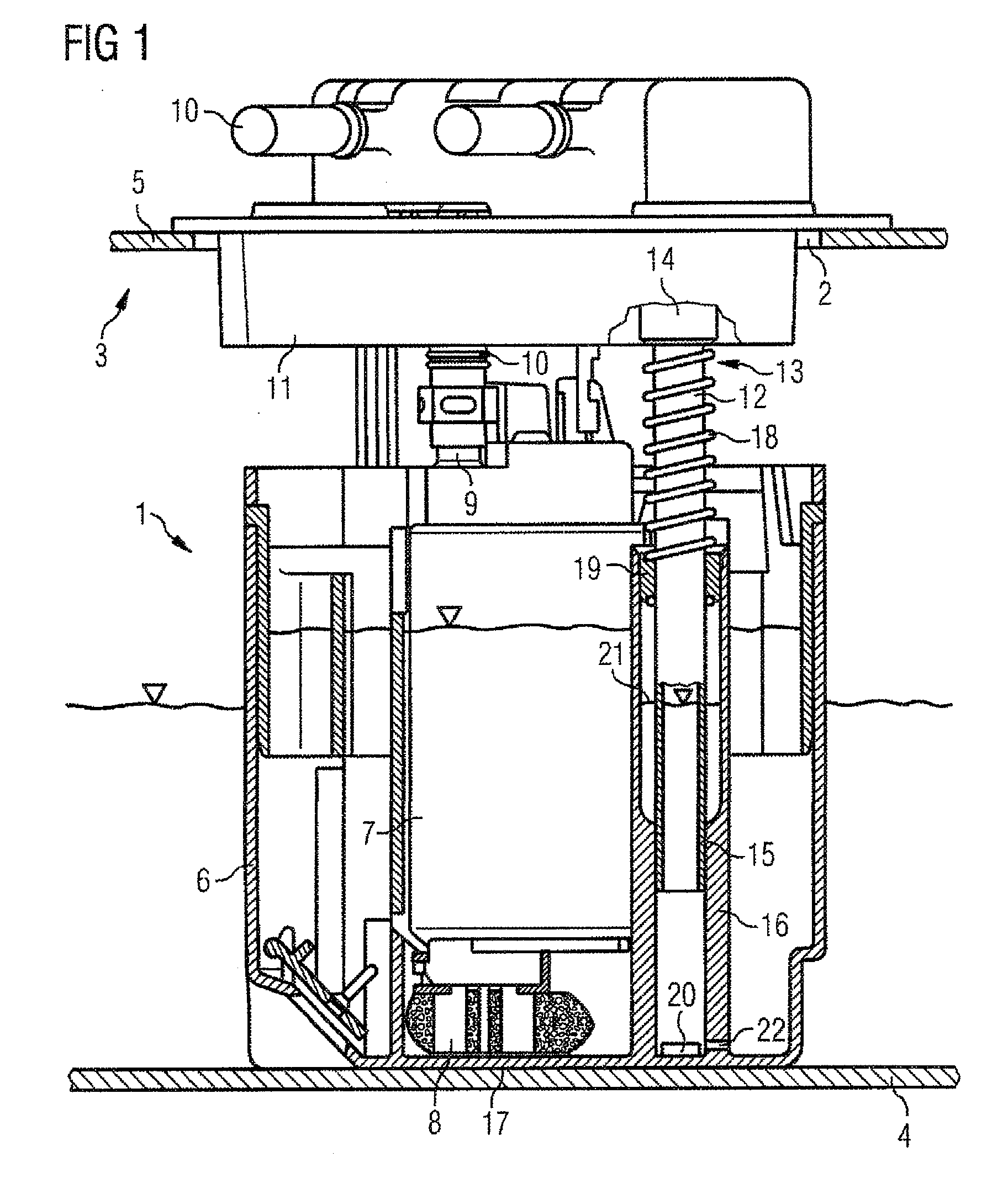
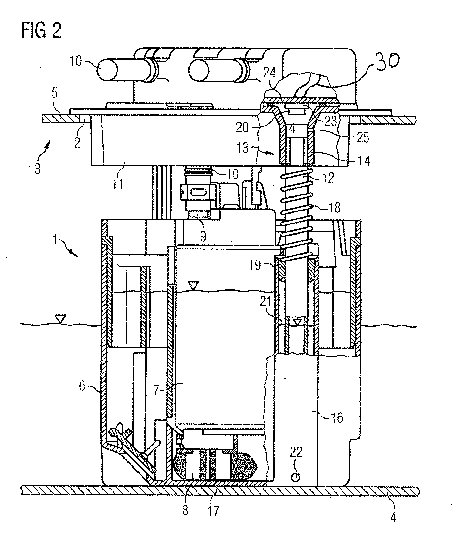
[0022]The fuel delivery unit 1 in FIG. 1 is inserted through an opening 2 into a fuel tank 3. The fuel tank 3 has a base 4 and an upper boundary wall 5. The fuel delivery unit 1 has a swirl pot 6, in which a fuel pump 7 is arranged, and a flange 11 which closes off the opening 2. The fuel pump 7 draws fuel from the swirl pot 6 via a pre-filter 8 and delivers the fuel via an outlet 9 into a feed line 10 which leads through the flange 11 to an internal combustion engine (not illustrated) of a motor vehicle.

[0023]The flange 11 and the swirl pot 6 of the fuel delivery unit 1 are connected to one another by a support element 12 designed as a circular tube. The connection to the flange 11 takes place by the upper region 13 of the tube 12. The upper region 13 is pressed into a bush 14 of the flange 11. The lower end 15 of the tube 12 is arranged in a receptacle 16 with a circular cross section, such that the tube 12 can slide along the receptacle 16. The receptacle 16 extends as far as the...


PUM


Abstract

A fuel delivery unit for insertion into a fuel tank of a motor vehicle has a swirl pot, a flange for closing an opening in the fuel tank, and a support element arranged between the flange and the swirl pot that prestresses the swirl pot towards a bottom of the fuel tank. A filling level sensor is arranged on the swirl pot. The swirl pot has at least one receptacle. The receptacle extends to a bottom of the swirl pot and completely surrounds the periphery of the support element and has an opening in the bottom region through which fuel from the fuel tank can enter the receptacle. The filling level sensor comprises a transmission and receiving unit for ultrasonic waves arranged in the fuel delivery unit such that the ultrasonic waves run in the receptacle and the support element.

Description

CROSS REFERENCE TO RELATED APPLICATION[0001]This is a U.S. national stage of application No. PCT / EP2008 / 061694, filed on Sep. 4, 2008. Priority is claimed on German Application No.: 10 2007 042 559.9 filed Sep. 7, 2007 the content of which is incorporated herein by reference.BACKGROUND OF THE INVENTION[0002]1. Field of the Invention[0003]The subject of the present invention is a fuel delivery unit that can be inserted into a fuel tank of a motor vehicle, comprising a swirl pot, a flange for closing off an opening in the fuel tank, at least one support element designed as a hollow profile arranged between the flange and the swirl pot that preloads the swirl pot against the base of the fuel tank comprising a filling level sensor arranged on the swirl pot.[0004]2. Description of the Prior Art[0005]Fuel delivery units of this type are frequently inserted into fuel tanks of modern motor vehicles and have therefore long been known. The support elements are generally tubes or rods which ar...

Claims


Application Information

Patent Timeline
IPC IPC(8): G01F23/296
CPCB60K15/00B60K15/077B60K2015/03111G01F23/296F02M37/103F02M37/106F02M37/14B60K2015/03217
Inventor RUMPF, BERND
Owner CONTINENTAL AUTOMOTIVE GMBH
Learn More