Solar air heater for heating air flow

Inactive Publication Date: 2010-07-29
ARNDT
View PDF8 Cites 18 Cited by
  • Summary
  • Abstract
  • Description
  • Claims
  • Application Information

AI Technical Summary

Benefits of technology

[0030]It is important that as much as possible of the thermal energy absorbed by the heat absorption element is transferred to the air passing said heat element, i.e. it is important that heat is not dissipated away from the solar air h

Problems solved by technology

Alternately if the solar air heater, due to limitations in the building construction, such

Method used


Image

  • Solar air heater for heating air flow
  • Solar air heater for heating air flow
  • Solar air heater for heating air flow

Examples


Embodiment Construction

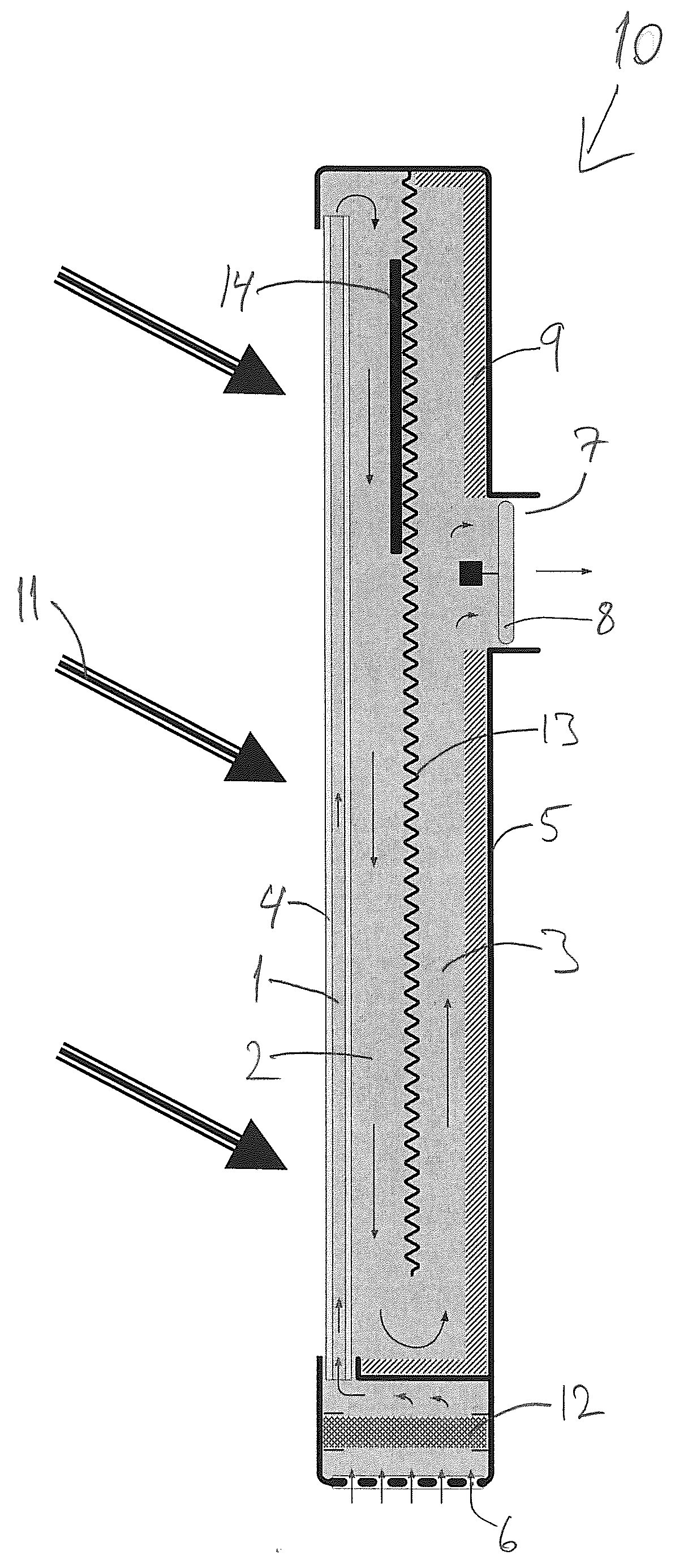
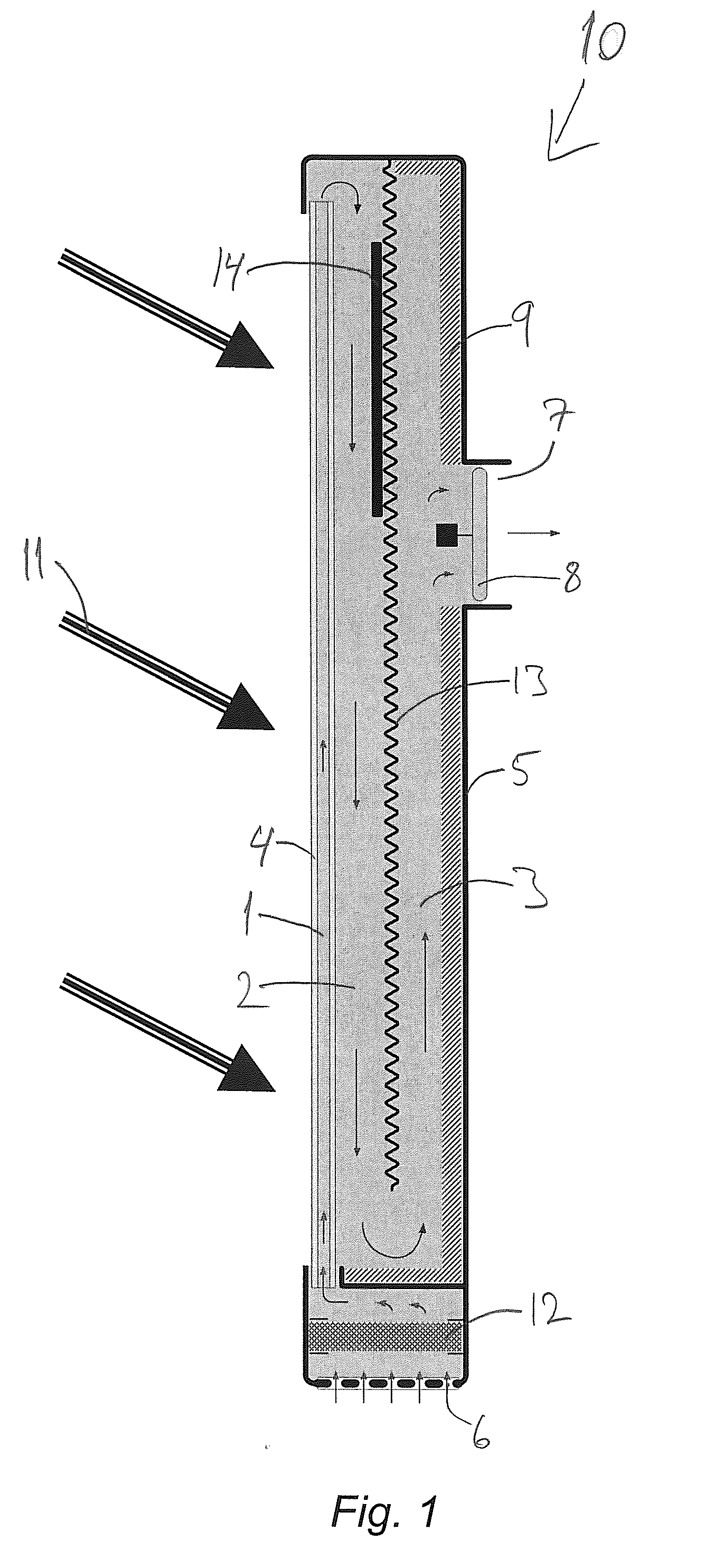
[0040]FIG. 1 shows a cross sectional side view of one embodiment of a solar air heater 10 according to the invention, wherein said solar air heater is in heating mode also known as winter mode. The airflow path inside the solar air heater 10 is indicated by arrows. Air enters the solar air heater 10 through an air inlet 6 comprising a plurality of holes in the bottom of the solar air heater 10. The air passes a filter 12 for removing and filtering out dust particles, filth and the like from the incoming air. The air is subsequently guided into a first flow passage 1, inside the translucent or transparent front panel 4. The front panel is preferably made of glass and / or a plastics material such as polycarbonate. The front panel 4 comprises at least two plates where between the first flow passage 1 is located. When the air passes through the first flow passage 1 it will be subject to heat from sunlight 11 passing through the translucent or transparent front panel 4. When the air exits...


PUM


Abstract

The invention relates to a solar air heater comprising—at least one transparent or translucent front panel comprising at least one first flow passage, said first flow passage substantially elongated and extending along the surface of the front panel,—a back panel preferably substantially parallel with the front panel,—at least one heat absorbing element, preferably located between the front panel and the back panel,—at least one air inlet,—at least one air outlet,—at least a second flow passage between the front panel and the heat absorption element, and—at least a third flow passage between the heat absorption element and the back panel, whereby air flowing through the solar air heater from an air inlet to an air outlet will pass at least a first, a second and a third flow passage. In a further embodiment of the invention the solar air heater comprises means for driving and/or inverting the airflow through said solar air heater, whereby heating and/or ventilation of a room and/or a building connected to said solar air heater can be provided.

Description

[0001]The present invention relates to a solar air heater for heating airflow and a method for same.BACKGROUND OF INVENTION[0002]With an increasing focus on global warming and the consequences thereof, renewable energy has attracted increasing interest lately. This combined with the growing demand for insulation of houses, possibly leading to increased humidity, thus providing a need for ventilation and / or improvement of the indoor climate. Also increasing energy prices help to guide consumers toward renewable energy sources, methods for saving energy and reducing energy expenses. Methods and devices for transforming the energy from the sunlight radiating the earth into heat and / or electricity have been known for years. The present application more specifically deals with heating and / or ventilation of buildings by utilizing nothing but sunlight.[0003]EP 1 448 937 B1 describes a solar collector panel for heating an airflow, wherein the solar collector panel comprises solar cells and ...

Claims


Application Information

Patent Timeline
IPC IPC(8): F24J2/04G05B15/00F24J2/00F24F7/00F24S10/50F24S10/55
CPCF24F5/0075Y02A30/272Y02B10/20Y02B10/24Y02B10/70Y02B30/92Y02E10/44Y02E10/60H02S40/44F24S10/55F24S20/67F24S70/60F24S10/25F24S20/66F24S10/503Y02A30/62Y02A30/26F24F2005/0064Y02B10/10Y02B30/90Y02E10/50Y02A30/00Y02A30/60
Inventor ARNDT, PAUL RIIS
Owner ARNDT
Why Eureka
Try Eureka