Method for collecting solar radiation and transforming it into heat energy

a technology of solar radiation and heat energy, applied in the field of solar thermal collection system, can solve the problems of not being suitable for the purposes, etc., and achieve the effect of minimizing heat loss during transportation and minimizing heat loss

Inactive Publication Date: 2021-01-21
FREEMAN WALTER B
View PDF1 Cites 0 Cited by
  • Summary
  • Abstract
  • Description
  • Claims
  • Application Information

AI Technical Summary

Benefits of technology

[0017]The present invention relates to a solar thermal collecting system that captures solar radiation and transforms it into heat energy; whereby the system provides a vessel that contains an opaque or partially opaque fluid medium that is defined by a predetermined thermal capacity; whereby the vessel comprises an at least partially transparent or translucent lid which in some applications include an integrated solar panel, which enables passage of solar radiation into the fluid medium; whereby multiple reflective parabolic mirrors integrated in the inner sidewalls of the vessel focus the solar radiation throughout the fluid medium to create hot zones therein; and whereby the heated fluid medium is transported for storage, or to a heat exchanger, or a boiler or to an energy recovery assembly adapted to produce power from low intensity thermal sources or to transfer heat for subsequent beneficial use with minimal heat loss; and whereby the fluid medium is carried in an insulated conduit to minimize loss of heat during transport.
[0018]According to an aspect of the present invention, a solar thermal collecting system, includes a vessel defined by an inner sidewall, an outer sidewall, and an opening, the sidewalls forming a cavity, the vessel being resilient to withstand variances in pressure and temperature; an opaque or partially opaque fluid medium defined by a predetermined thermal capacity, the fluid medium disposed to at least partially fill the cavity of the vessel; a lid covering the opening in the vessel, the lid defined by an at least partially transparent or translucent lid, whereby the lid enables passage of solar radiation into the cavity; multiple mirrors / reflective surfaces integrated into the inner sidewall of the vessel, the mirrors focusing the solar radiation throughout the fluid medium to create hot zones in the fluid medium, the hot zones heating the fluid medium to the predetermined thermal capacity; an insulated conduit in communication with the vessel, the insulated conduit carrying the heated fluid medium to a second vessel for storage, or to a heat exchanger, or a boiler or to an energy recovery assembly adapted to produce power from low intensity thermal sources, whereby the insulation minimizes the amount of heat lost during transport of the fluid medium.
[0019]In view of the foregoing, it is therefore an objective of the present invention to provide a solar thermal collecting system that enhances the heat generated in the vessel through use of multiple parabolic mirrors that focus the solar radiation onto the fluid medium to create hot zones.
[0021]Yet another objective is to quickly transport the heated medium for storage to a boiler or energy conversion with minimal loss of heat through an insulated conduit.

Problems solved by technology

Even though these innovations may be suitable for the specific purposes to which they address, however, they would not be suitable for the purposes of the present invention.
Furthermore, even though these innovations may be suitable for the specific purposes to which they address, accordingly, they would not be suitable for the purposes of the present invention as heretofore described.

Method used


Image

  • Method for collecting solar radiation and transforming it into heat energy
  • Method for collecting solar radiation and transforming it into heat energy
  • Method for collecting solar radiation and transforming it into heat energy

Examples


Embodiment Construction

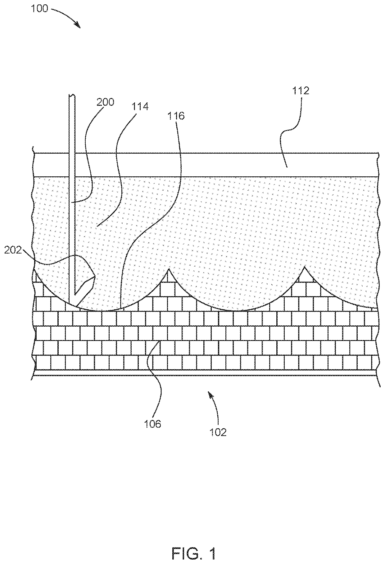
[0033]The following detailed description is merely exemplary in nature and is not intended to limit the described embodiments or the application and uses of the described embodiments. As used herein, the word “exemplary” or “illustrative” means “serving as an example, instance, or illustration.” Any implementation described herein as “exemplary” or “illustrative” is not necessarily to be construed as preferred or advantageous over other implementations. All of the implementations described below are exemplary implementations provided to enable persons skilled in the art to make or use the embodiments of the disclosure and are not intended to limit the scope of the disclosure, which is defined by the claims. For purposes of description herein, the terms “upper,”“lower,”“left,”“rear,”“right,”“front,”“vertical,”“horizontal,” and derivatives thereof shall relate to the invention as oriented in FIG. 1. Furthermore, there is no intention to be bound by any expressed or implied theory pres...


PUM


Abstract

A solar thermal collecting system captures solar radiation into a vessel containing an opaque or partially opaque fluid medium. The solar radiation is reflected and intensified using interior parabolic reflectors inside the vessel to generate hot zones throughout the fluid medium; and the generated heat in the fluid medium is transported to a separate system designed to utilize the heat with minimal heat loss. The system of the present invention comprises a vessel that contains the fluid medium. An at least partially transparent or translucent lid enables passage of solar radiation into the vessel. The lid may have integrated solar panels to generate power from solar radiation. Multiple reflective parabolic reflectors integrated in the vessel focus solar radiation throughout the fluid medium to create hot zones that intensifies heating the fluid medium. The vessel is resilient to withstand variances in pressure and temperature. After fluid medium absorbs heat, an insulated conduit transports the heated fluid medium for storage or other beneficial uses such as conversion to power with minimal heat loss.

Description

CROSS-REFERENCE TO RELATED APPLICATIONS[0001]This application is a divisional patent application of U.S. Ser. No. 16 / 038,917 entitled “Solar Thermal Collecting System”, filed on Jul. 18, 20218, which claims priority from U.S. Provisional Application Ser. No. 62 / 540,234, entitled “Solar Thermal Collecting System”, filed on Aug. 2, 2017, which applications are hereby incorporated herein by reference in their entirety.FIELD OF THE INVENTION[0002]The present invention relates generally to a solar thermal collecting system. More so, the present invention relates to a solar thermal collecting system that captures solar radiation and transforms it into heat energy.BACKGROUND OF THE INVENTION[0003]Various devices have been developed for collecting solar heat in order to render it usable either directly or as a supplement to fuel energy for heating a fluid medium. Many of the known devices would provide radiation-receptive panels inclined across the path of sunlight, together with a means fo...

Claims


Application Information

Patent Timeline
Patent Type & Authority Applications(United States)
IPC IPC(8): F24S10/70H01L31/054H02S40/22F24S23/30H01L31/048
CPCF24S10/70H01L31/0547H01L31/048H02S40/22F24S23/30H01L31/0543Y02E10/44Y02E10/52H02S40/44F24S23/71F24S23/74F24S60/30F24S80/20F24S80/457F24S40/57F24S2023/84Y02E10/60
Inventor FREEMAN, WALTER B.
Owner FREEMAN WALTER B
Why Eureka
Try Eureka