
Closed-circuit power line communication system for large capacity load

a technology of power line communication and large capacity, applied in the direction of power distribution line transmission, line transmission, electrical equipment, etc., can solve the problems of reducing the communication speed, reducing the impedance, and almost shortening the device, so as to reduce the heat generated by the semiconductor switching device, reduce the space, and save costs

Active Publication Date: 2015-12-08
UNILUX INC
View PDF4 Cites 0 Cited by
  • Summary
  • Abstract
  • Description
  • Claims
  • Application Information

AI Technical Summary

Benefits of technology

[0054]Since a first switch manufactured using a semiconductor switching device and a second switch manufactured using a mechanical relay switching device are configured in parallel in a transmission means, and an amount of heat generated by the semiconductor switching device is minimized by cutting off the second switch and performing a communication operation through the first switch when a communication is performed and short-circuiting the second switch to flow current through the second switch when a communication is not performed, the present invention as described above provides an advantage of saving cost and reducing space without the need of a large scale semiconductor switching device and a large capacity heat sink plate.
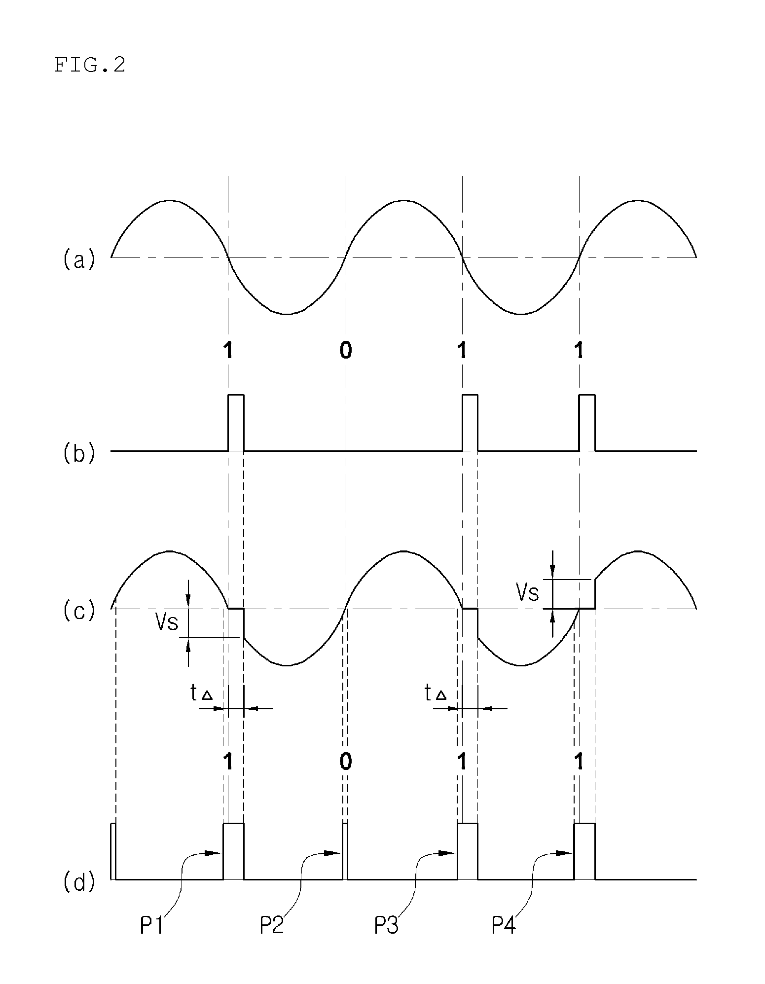
[0055]In addition, since a pulse signal for a communication signal having a comparatively large pulse width is generated by cutting off the power around a zero cross of a power waveform in order to generate the communication signal, the present invention provides an advantage of greatly improving a recognition rate and accuracy of the communication signal.
[0056]Furthermore, since a thermistor is further connected to a semiconductor switching device of a transmission means in series, the present invention fundamentally prevents burn-out of the first and second switches caused by inrush current when an initial power is supplied.
[0057]In addition, since an address setting unit is added in the reception and load means, the present invention provides an advantage of freely setting an individual ID of a control target illumination lamp.

Problems solved by technology

However, a communication signal modulated by the power line communication method acts as a noise in a general device which is connected to the same power system and does not desire communication.
In addition, when a certain device connected to the power system generates a lot of noises, a communication error occurs, and thus the communication speed is lowered.
In addition, the modulated signal generally has a high frequency, and if a peripheral device having a condenser at an input unit exists in the power system, impedance is lowered greatly for a corresponding modulated signal, and this will almost short-circuits the device, and the signal cannot be transferred to a far distance.
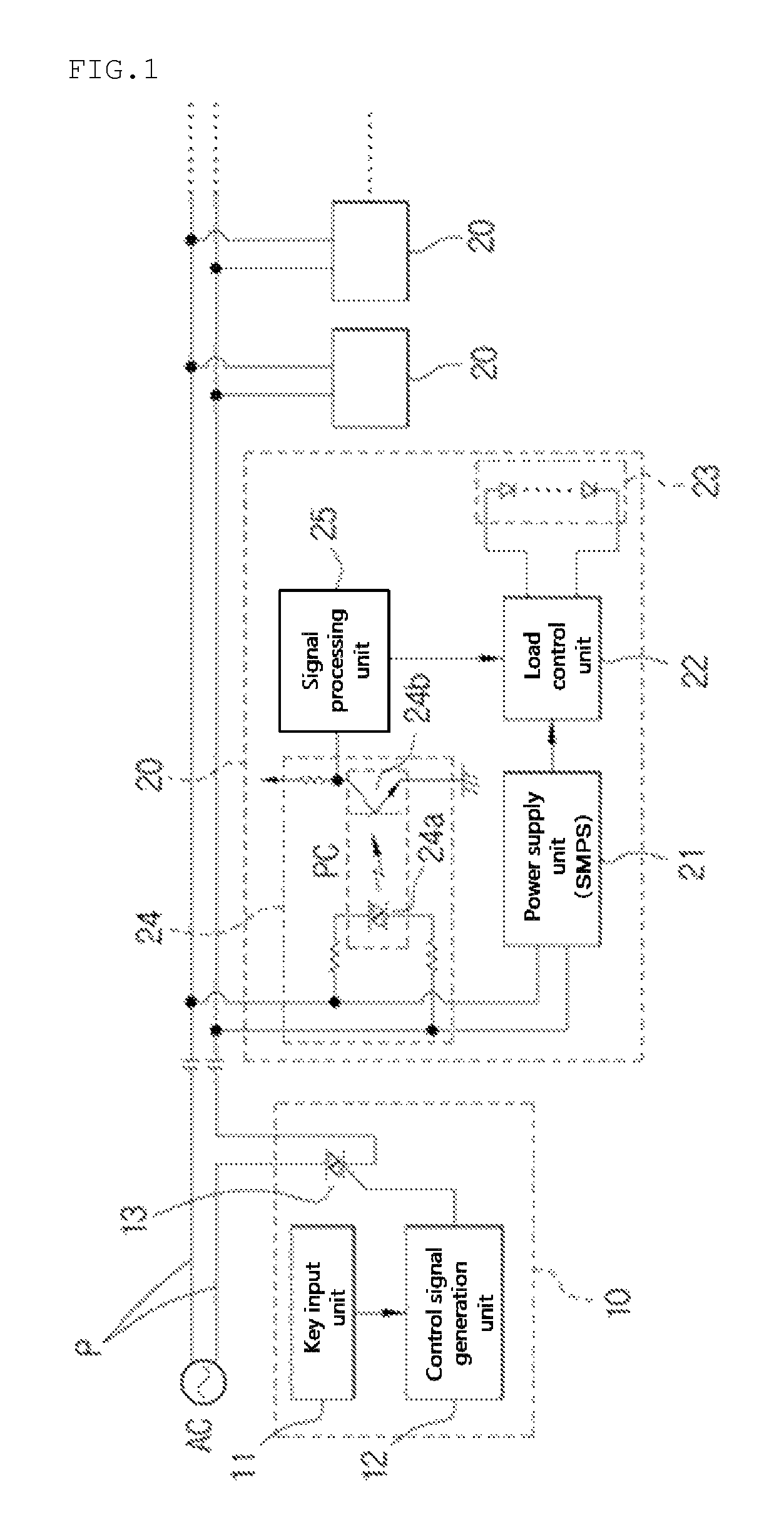
However, such a power line communication system has problems described below.
As described above, if the voltage Vs at the time point of turning on the switching device 13 is increased, a switching noise is generated.
Due to such phenomena, there is a problem of cost and space since a semiconductor switching device having a large current capacity and a heat sink plate of a large capacity should be used.
In addition, there is a problem in that a lot of electrical energy is lost in the form of heat as the heat is generated.
Third, if a load has a high inrush current due to a large condenser component, there is a problem in that the semiconductor switching device 13 is destroyed since an extremely high inrush current flows when several loads are connected in parallel.

Method used


Image

  • Closed-circuit power line communication system for large capacity load
  • Closed-circuit power line communication system for large capacity load
  • Closed-circuit power line communication system for large capacity load

Examples


Embodiment Construction

[0062]Hereafter, the preferred embodiments of the present invention will be described in detail with reference to the accompanying drawings.

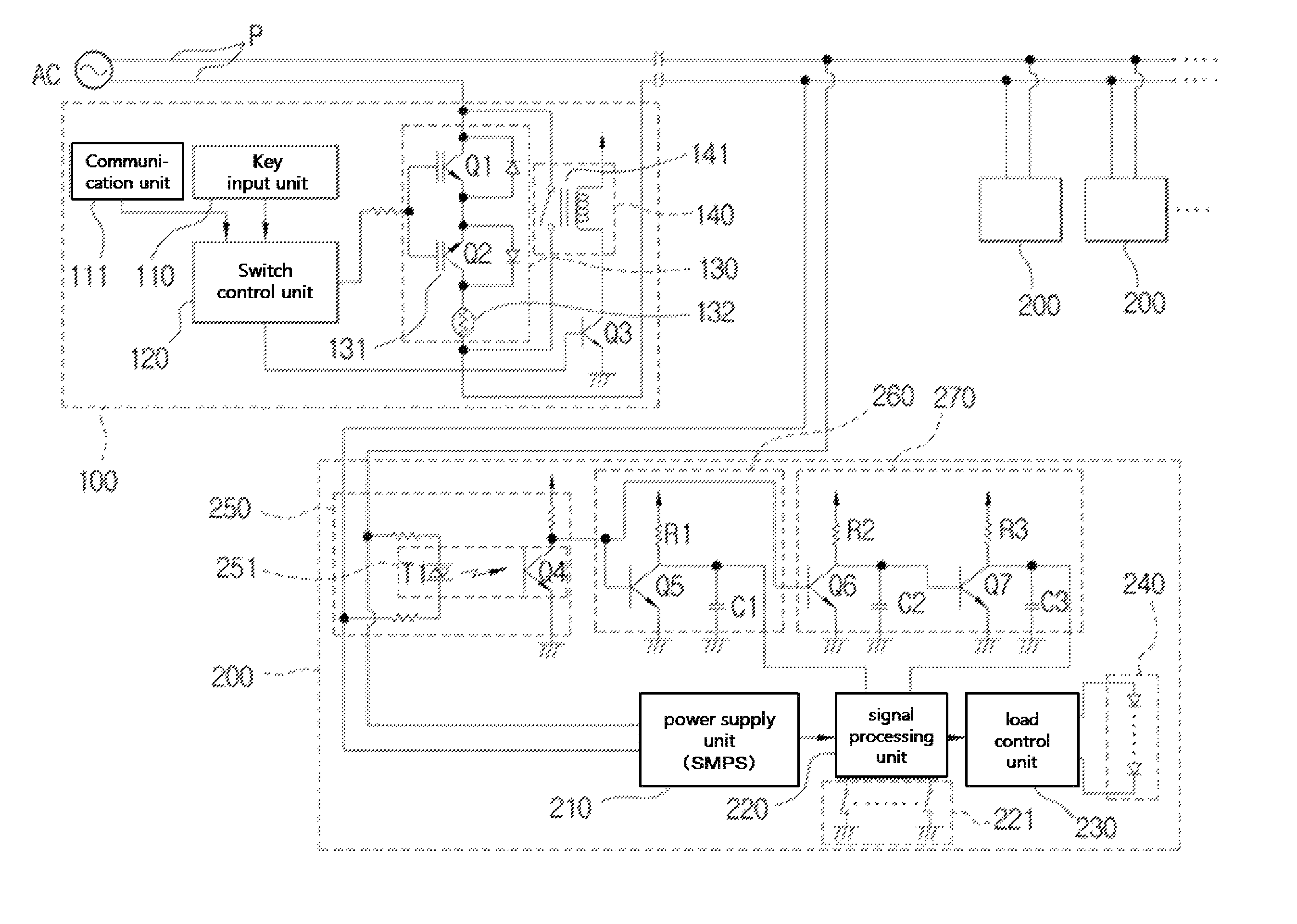
[0063]FIG. 3 is a view showing the configuration of a power line communication system for a large capacity load according to the present invention.

[0064]As shown in the figure, the power line communication system for a large capacity load according to the present invention includes a transmission means 100 connected to one side of the power line P in series to generate a communication signal and transmit the communication signal through the power line, and a plurality of reception and load means 200 connected to both sides of the power line P in parallel to receive the communication signal transmitted through the power line and control a corresponding load.

[0065]The transmission means 100 includes at least a switching control unit 120 for generating and transferring a switching control signal to a first switch unit 130 and a second switch unit 1...


PUM


Abstract

The present invention relates to a power line communication system for a large capacity load which greatly improves the recognition ratio and accuracy of a communication signal even for a large capacity load in that it: includes a switch unit as a transmission means wherein a first switch made of semiconductor elements and a second switch made of relay elements are connected in parallel; and generates and transmits a communication signal by selectively using the switches.

Description

TECHNICAL FIELD[0001]The present invention relates to a closed-circuit power line communication system, and more specifically, to a closed-circuit power line communication system for a large capacity load, which improves greatly a recognition rate and an accuracy of a communication signal even for the large capacity load by configuring a switch unit in a transmission means by connecting a first switch manufactured using a semiconductor switching device and a second switch manufactured using a relay switching device in parallel and generating and transmitting a communication signal by selectively using the switches.BACKGROUND ART[0002]Generally, in most cases, power line communication uses a method of modulating a signal (a communication signal) desired to communicate and overlapping the modulated signal on a power line to which a corresponding device is connected.[0003]However, a communication signal modulated by the power line communication method acts as a noise in a general devic...

Claims


Application Information

Patent Timeline
Patent Type & Authority Patents(United States)
IPC IPC(8): H04B3/56H04B3/54H04B3/58
CPCH04B3/56H04B3/542H04B3/58H04B2203/542H04B2203/5412
Inventor KIM, JUNG-HO
Owner UNILUX INC
Learn More