Travel drive apparatus for a working vehicle

a technology for working vehicles and drive apparatuses, which is applied in the direction of engine-driven generators, machines/engines, propulsion parts, etc., can solve the problems of inability to act on the lubricant pump sucking lubricant oil, and achieve the effects of enhancing lubrication performance and cooling performance, preventing the lubricant pump from being driven wastefully, and lowering the temperature of lubricant oil flowing in and out of the wheel mounting case through circulation lines

Active Publication Date: 2010-07-29
NIHON KENKI CO LTD
View PDF6 Cites 33 Cited by
  • Summary
  • Abstract
  • Description
  • Claims
  • Application Information

AI Technical Summary

Benefits of technology

[0019]With the arrangements just described, under the condition in which the vehicle has been warmed up after the start of the engine and has assumed the state of steady operation, the lubricant pump can be started by driving the electric motor when the rotational speed of the wheel (travel speed of the vehicle) is lower than a predetermined determination speed, thereby forcibly circulating the lubricant oil pooled in a wheel mounting case. In consequence, the temperature of the lubricant oil which flows in and outside the wheel mounting case through circulation lines can be lowered by using an oil cooler, and the lubricant oil whose oil temperature is low can be supplied to the reduction gear mechanism inside the wheel mounting case, thereby making it possible to enhance the lubrication performance and cooling performance. Moreover, in this state, when the rotational speed of the wheel (travel speed of the vehicle) has become faster than the predetermined determination speed, the lubricant oil in the wheel mounting case behaves in such a manner as to stick to the entire periphery of the inner wall surface of the wheel mounting case under the influence of centrifugal force, so that there is a possibility that the action of sucking the lubricant oil by the lubricant pump becomes impossible. Accordingly, in such a case, the control means stops the drive of the lubricant pump by the electric motor and makes it possible to prevent the lubricant pump from assuming an idling state and continuing dry operation.
[0020]Meanwhile, in the initial stage when the vehicle has started a warm-up operation by the start of the engine, unless the lubricant pump is initially started by the electric motor, the lubricant oil pooled in the wheel mounting case will not be sent to the position of the oil temperature sensor, so that the temperature of the lubricant oil cannot be detected by the oil temperature sensor. However, in the initial stage of such vehicle operation, the temperature of the drive source is relatively low, and it is known that the temperature of the lubricant oil pooled in the wheel mounting case and the temperature of the drive source are in a substantially equivalent state. Accordingly, by estimating the temperature of the lubricant oil from the temperature of the drive source, the drive of the lubricant pump by the electric motor can be stopped until the temperature of the drive source rises to a predetermined temperature at which the cooling of the lubricant oil by forced circulation is required. In consequence, it is possible to prevent the lubricant pump from being driven wastefully, making it possible to attain energy saving.

Problems solved by technology

Moreover, in this state, when the rotational speed of the wheel (travel speed of the vehicle) has become faster than the predetermined determination speed, the lubricant oil in the wheel mounting case behaves in such a manner as to stick to the entire periphery of the inner wall surface of the wheel mounting case under the influence of centrifugal force, so that there is a possibility that the action of sucking the lubricant oil by the lubricant pump becomes impossible.

Method used


Image

  • Travel drive apparatus for a working vehicle
  • Travel drive apparatus for a working vehicle
  • Travel drive apparatus for a working vehicle

Examples


Embodiment Construction

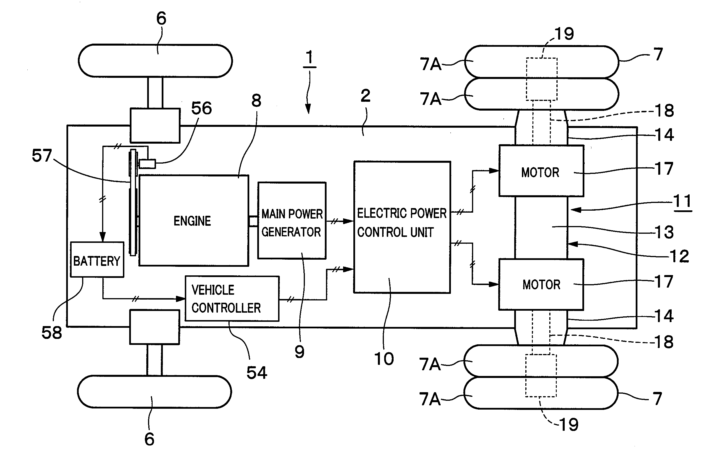
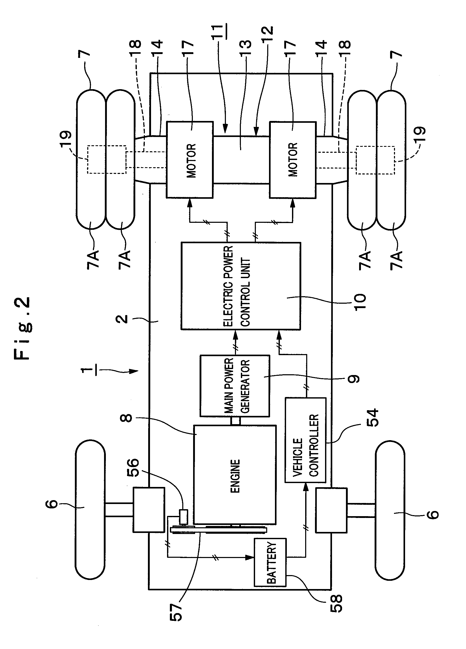
[0037]Hereafter, with reference to FIGS. 1 to 8 of the accompanying drawings, a detailed description will be given of the travel drive apparatus for a working vehicle in accordance with an embodiment of the present invention by citing as an example a case in which the present invention is applied to a rear drive type dump truck.

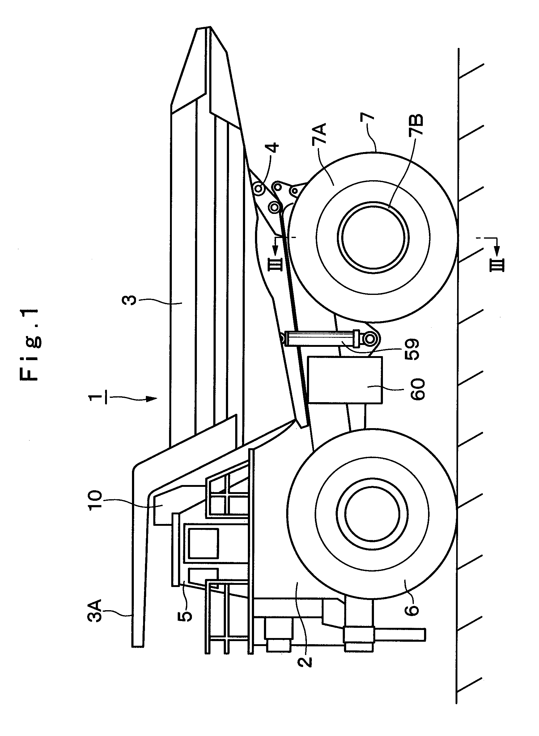
[0038]In the drawings, indicated at 1 is a dump truck as a typical working vehicle. As shown in FIG. 1, the dump truck 1 is built with a sturdy frame structure, and largely constituted by an automotive vehicle body 2 with below-described front and rear wheels 6 and 7 serving as wheels, and a vessel 3 which is liftably mounted on the vehicle body 2 as a load-carrying platform.

[0039]Further, the vessel 3 is formed as a large-size container whose overall length reaches as much as 10 to 13 meters to load a large volume of heavy load such as crushed stones or other similar objects, and its rear side bottom portion is liftably (tiltably) coupled to a rear end side ...


PUM


Abstract

In case a temperature (T) of a lubricant oil (G) cannot be detected by an oil temperature sensor (51) provided on an output side of a lubricant pump (46), the temperature (Tm) of a wheel drive motor (17) is detected by using a motor temperature sensor (53) provided on the wheel drive motor (17). By estimating the temperature (T) of the lubricant oil (G) from the temperature (Tm) of the wheel drive motor (17), monitoring is carried out as to whether or not the temperature (Tm) has risen to a predetermined temperature (Tms) at which the cooling of the lubricant oil (G) by forced circulation is deemed necessary. The drive of a lubricant pump (46) by a pump drive motor (47) is stopped until the motor temperature (Tm) rises to a level exceeding the predetermined temperature (Tms).

Description

BACKGROUND ART[0001]1. Field of the Invention[0002]The present invention relates to a travel drive apparatus for a working vehicle such as a large-size transportation vehicle and dump truck which is suitably used in transporting crushed stones excavated from a mine or the like.[0003]2. Description of the Prior Art[0004]Generally, large-size transportation vehicles, called dump trucks, have a liftable vessel (a loading platform) on a frame of a vehicle body, and carry heavy objects to be transported like crushed stones in a state in which the objects to be transported are loaded in a large quantity on the vessel.[0005]In this regard, for example, a travel drive apparatus which is adapted to drive a drive wheel of a dump truck is provided with a tubular axle housing which is mounted on a vehicle body, a drive source such as an electric motor or a hydraulic motor which is provided in the axle housing and rotationally drives a rotational shaft, a wheel mounting case rotatably mounted ar...

Claims


Application Information

Patent Timeline
Patent Type & Authority Applications(United States)
IPC IPC(8): F16N7/38G06F19/00B60K6/365B60K6/46B60K7/00B60L15/20B60L50/10B60W10/08B60W10/30B60W20/00F16H1/28F16H59/72F16H61/00
CPCB60B11/06B60K17/046F16H57/0434Y02T10/7258Y02T10/72
Inventor NABESHIMA, YOSHIFUMIMURAHASHI, TAKAYOSHIMINOSHIMA, TOSHIKAZUWATANABE, YUTAKA
Owner NIHON KENKI CO LTD
Why Eureka
Try Eureka