Light emitting diode linear light for machine vision

a technology of light-emitting diodes and machine vision, which is applied in the direction of lighting support devices, instruments, condensers, etc., can solve the problems of slow deformation rate of lamps, low cost of lamps, and cost of shutting down a line to replace lamps, etc., to achieve improved thermal and optical performance, compact and reliable design, and high thermal conductivity

Active Publication Date: 2010-07-29
INNOVATIONS & OPTICS
View PDF20 Cites 37 Cited by
  • Summary
  • Abstract
  • Description
  • Claims
  • Application Information

AI Technical Summary

Benefits of technology

[0009]The invention herein describes a linear lighting system which incorporates light emitting diode (LED) light sources with one or more distinct colors including broad band white light, ultraviolet, and near infrared. The LED die or die arrays are mounted to a high thermal conductivity circuit board comprising COB technology which can include both the LED die and electronic drive components resulting in a more compact and reliable design with improved thermal and optical performance at lower cost relative to pre-packaged based LED systems and other non LED systems such as the industry standard tungsten halogen lamp coupled to optical fibers arranged in a line. In conjunction with high efficiency imaging collection optics and aberration corrected cylindrical optics, the resulting LED based line source of the present invention is unmatched in performance by any other commercially available line source lighting system. The approach of modular LED modules and lens units internal to the line source housing minimizes overall system cost to the user and can be provided in any desired length. This is a lower cost approach relative to providing complete stand alone modular sections that can be combined into longer sections due to the reduced cost of the bill of materials and electronic drive complexity.

Problems solved by technology

High brightness light emitting diode (LED) light sources are in high demand for challenging applications in machine vision.
One of the most serious limitations of tungsten halogen technology is that the intensity of the lamps degrades at a fast rate.
The cost of the lamps is not the primary concern, however.
It is the cost of shutting down a line to replace the lamp that is primarily driving the need for LED based systems.

Method used


Image

  • Light emitting diode linear light for machine vision
  • Light emitting diode linear light for machine vision
  • Light emitting diode linear light for machine vision

Examples


Embodiment Construction

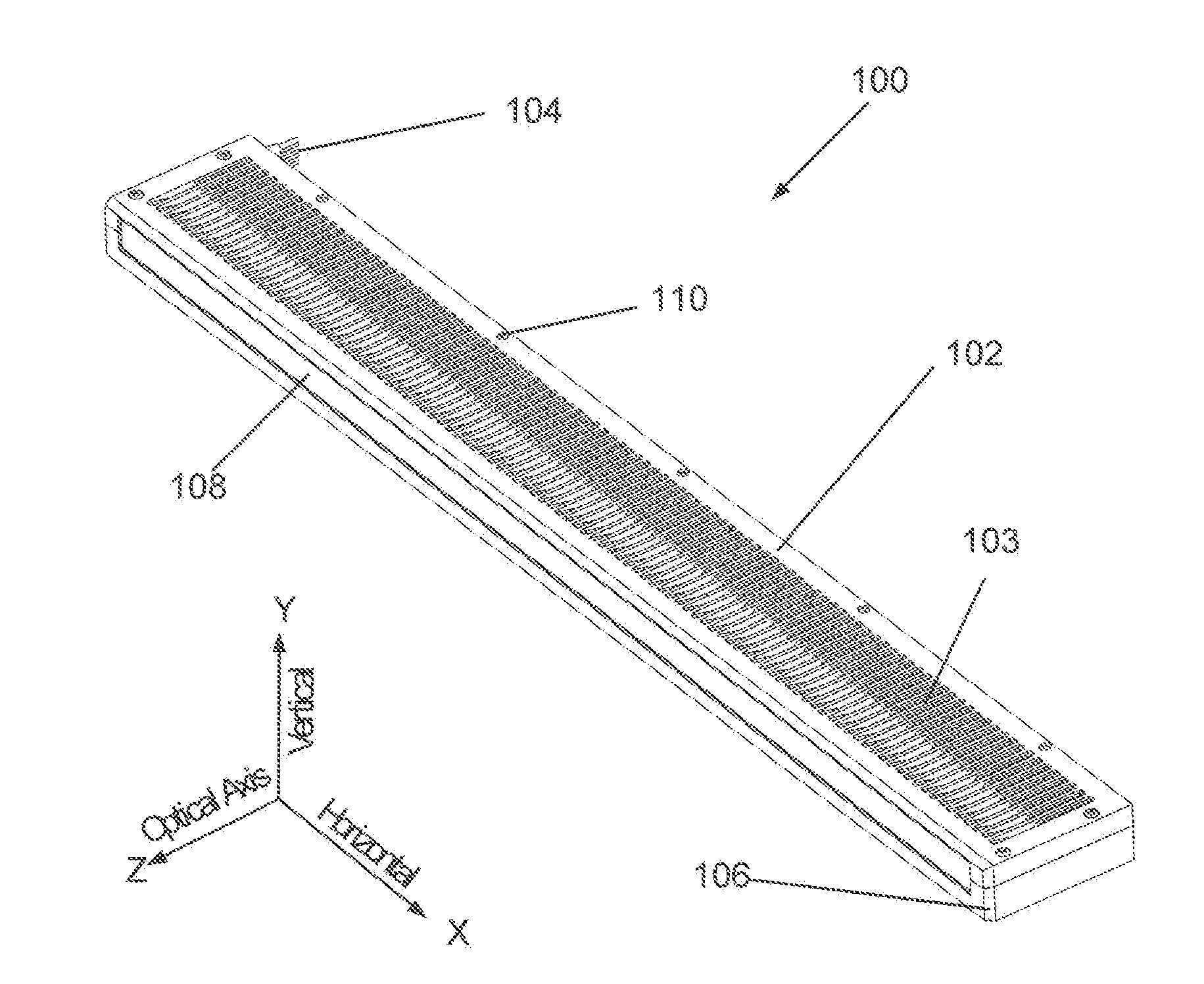
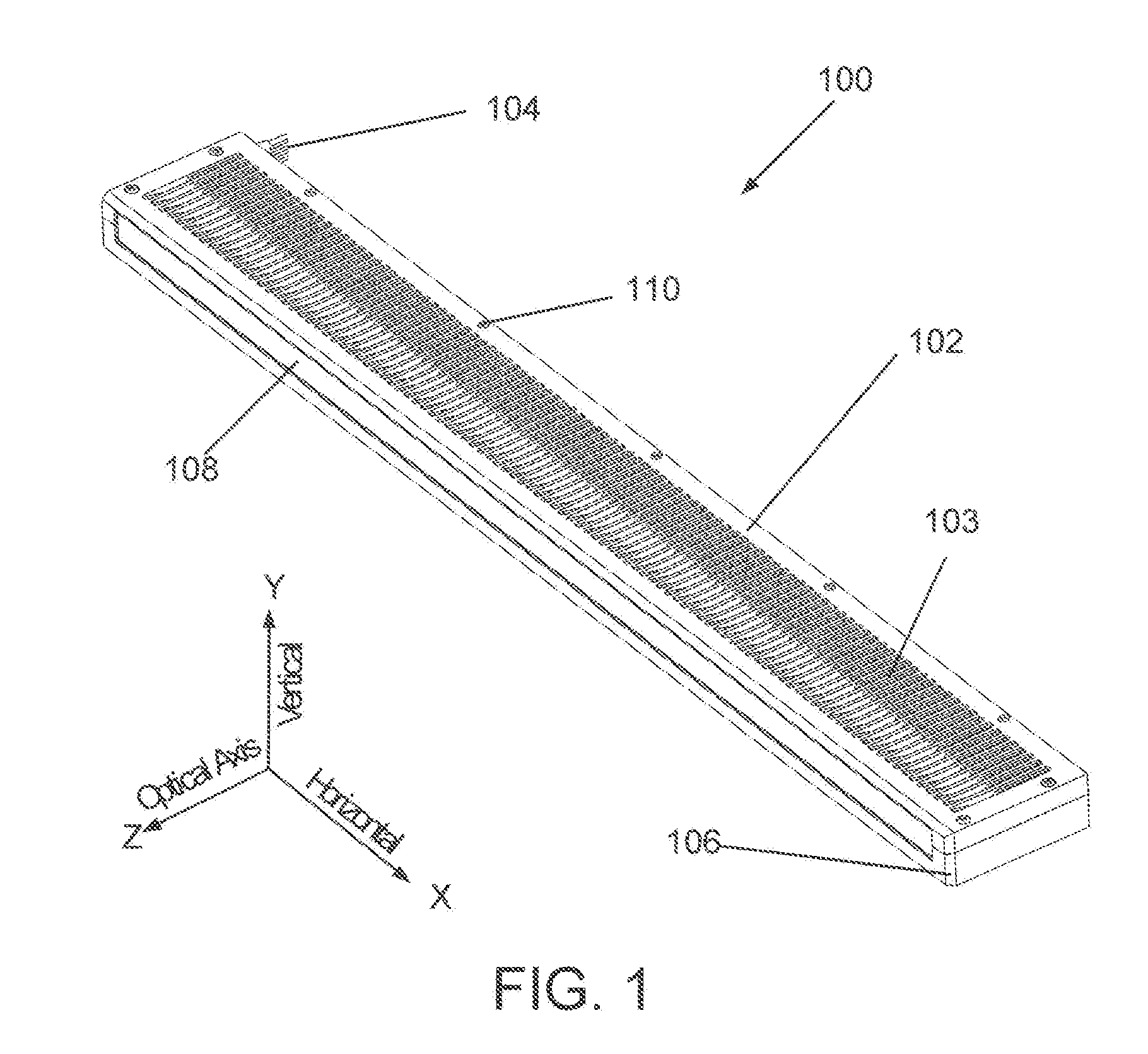
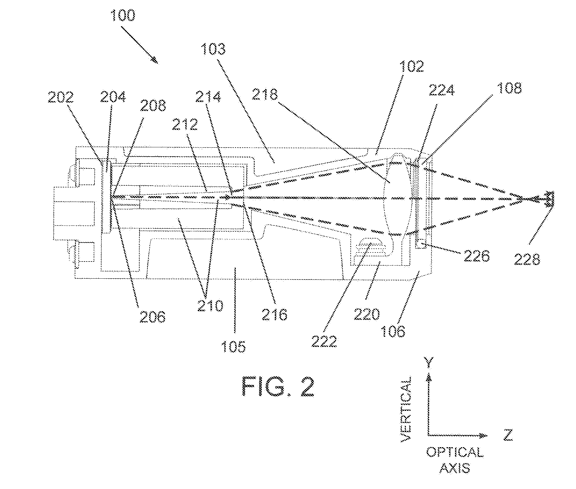
[0038]The present invention relates to Light Emitting Diode (LED) lighting arranged to produce a line of uniform high intensity light suitable for illuminating the field of view of line scan cameras for use in machine vision applications or the like. In particular, the present invention represents an LED based light source for improved line scan and web inspection systems in a more compact form factor, low cost, higher intensity, and increased lifetime relative to previous sources. The present invention also has application to edge lighting of planar light guides for backlighting large area Liquid Crystal Television Displays (LCDs) and similarly for backlighting for commercial signage. Yet another application is for structured under counter lighting and tube type fluorescent lamps.

[0039]We define prepackaged LEDs as devices comprising an LED die or die array sitting on top of one or more thermally and electrically conductive materials each with associated thermal impedance with elec...


PUM


Abstract

The invention herein comprises a linear lighting system which incorporates light emitting diode (LED) light sources with one or more distinct colors including broad band white light. The LED die or die arrays are mounted to a high thermal conductivity circuit board comprising COB technology which can include both the LED die and electronic drive components resulting in a more compact and reliable design with improved thermal and optical performance at lower cost. In conjunction with high efficiency imaging collection optics and aberration corrected cylindrical optics, the output of the LED sources are imaged to a bright line suitable for use in machine vision applications and the like.

Description

CROSS REFERENCE TO RELATED APPLICATION[0001]This application claims priority from U.S. Provisional Patent Application No. 61 / 147,436 entitled LIGHT EMITTING DIODE LINEAR LIGHT FOR MACHINE VISION and filed on Jan. 26, 2009 in the name of Thomas J. Brukilacchio, the entire contents of which are incorporated herein by reference.FIELD OF THE INVENTION[0002]This invention, in general, relates to providing a continuous high intensity line of light suitable for illuminating the field of view of linear imaging systems typically used in machine vision applications and, more particularly, to the use of light emitting diodes (LEDs) in high intensity linear lighting systems. Other applications that could make use of such a lighting system include edge illuminated backlighting for large screen televisions, commercial signage, and linear tube fluorescent LED replacement lamps.BACKGROUND OF THE INVENTION[0003]High brightness light emitting diode (LED) light sources are in high demand for challengi...

Claims


Application Information

Patent Timeline
Patent Type & Authority Applications(United States)
IPC IPC(8): H05B37/02F21S4/00F21V1/00F21V9/16H05B44/00
CPCG02B5/021G02B5/0278G02B6/0006G02B6/0008G02B19/0028G02B27/0994H05B33/0803H05B33/0857G02B19/0066G02B27/0966H05B45/20H05B45/00
Inventor BRUKILACCHIO, THOMAS J.
Owner INNOVATIONS & OPTICS
Why Eureka
Try Eureka