Antenna duplexer and communication apparatus employing the same

a technology of communication apparatus and duplexer, which is applied in the field of antenna duplexer, can solve the problems that the conventional antenna duplexer is difficult to be downsized, and achieve the effect of downsizing the communication equipment and the antenna duplexer

Active Publication Date: 2010-07-29
SKYWORKS PANASONIC FILTER SOLUTIONS JAPAN
View PDF16 Cites 27 Cited by
  • Summary
  • Abstract
  • Description
  • Claims
  • Application Information

AI Technical Summary

Benefits of technology

[0008]This structure enables the use of the third filter for both first band and the second band. Accordingly, at least one filter can be eliminated in line with every increase in the number of selectable bands, contributing to downsizing of antenna duplexer. Furthermore, the present invention achieves downsizing of communications equipment by the shared use of a transmit amplifier and a low-noise amplifier connected to the antenna duplexer between the first band and the second band.

Problems solved by technology

However, this conventional antenna duplexer is difficult to be downsized.

Method used


Image

  • Antenna duplexer and communication apparatus employing the same
  • Antenna duplexer and communication apparatus employing the same
  • Antenna duplexer and communication apparatus employing the same

Examples


first exemplary embodiment

[0033]An antenna duplexer in the first exemplary embodiment of the present invention is described below with reference to drawings.

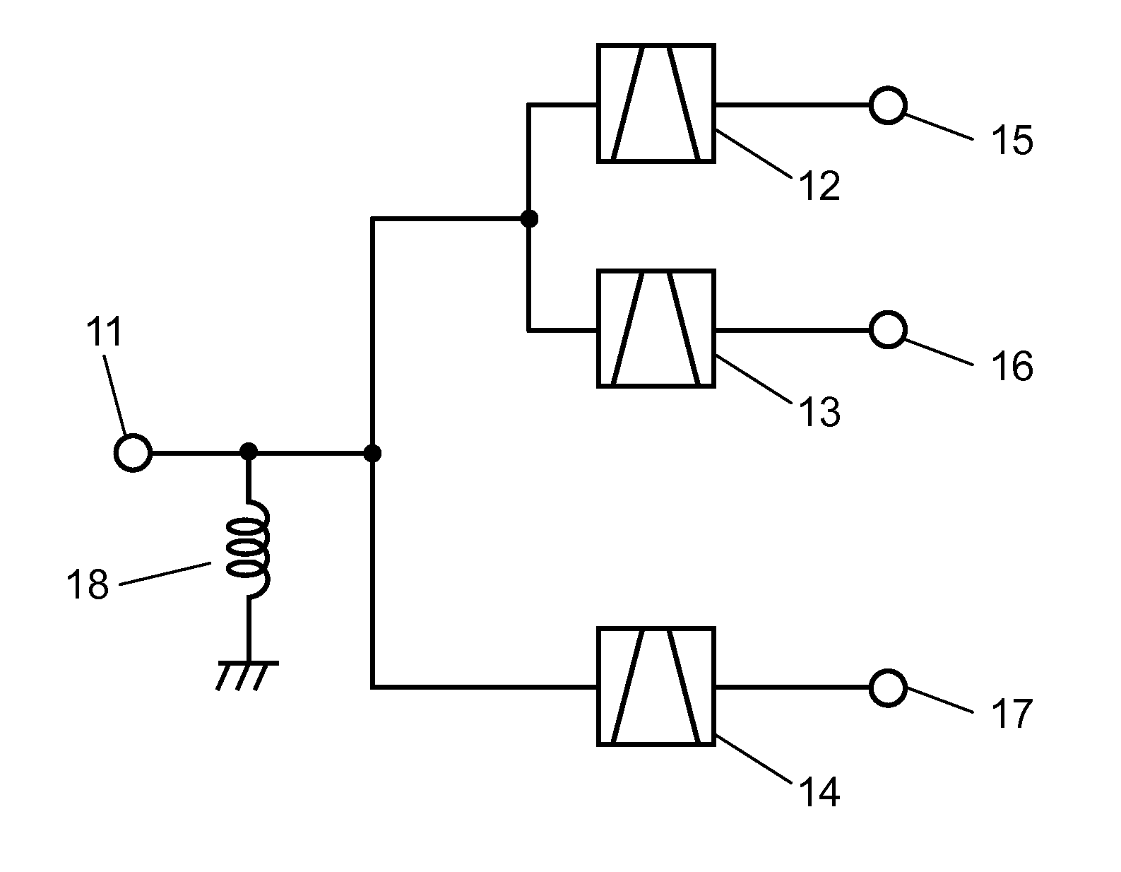
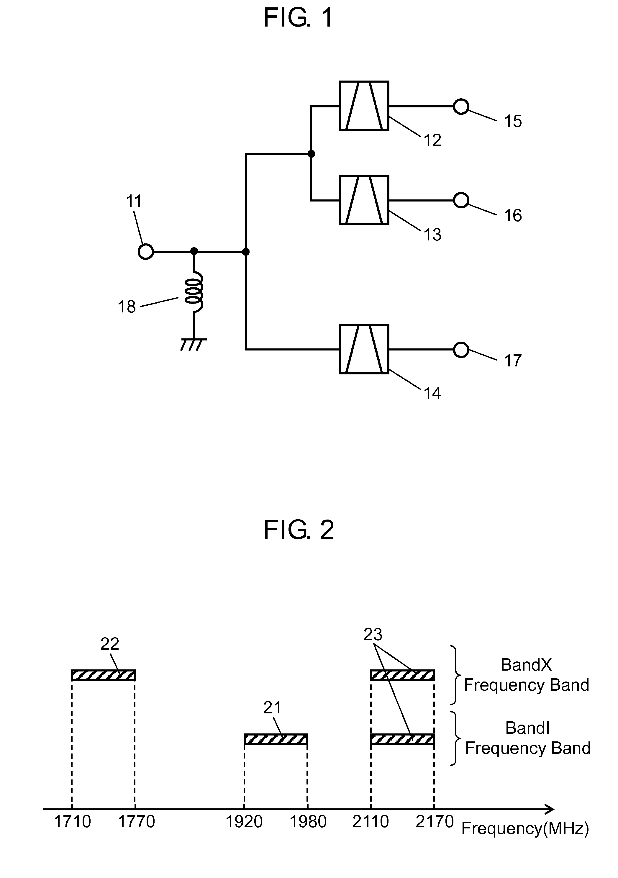
[0034]FIG. 1 is a diagram of the antenna duplexer in the first exemplary embodiment of the present invention. In antenna duplexer in the first exemplary embodiment, shown in FIG. 1, antenna terminal 11, which is connected to an antenna, is connected to first filter 12, second filter 13, and third filter 14. One end of first filter 12 is electrically connected to this antenna terminal 11, and the other end is connected to transmit terminal 15. One end of second filter 13 is electrically connected to this antenna terminal 11, and the other end is connected to transmit terminal 16. One end of third filter 14 is electrically connected to this antenna terminal 11, and the other end is connected to receive terminal 17. Antenna terminal 11 is ground via inductor 18 serving as a matching circuit.

[0035]FIG. 2 illustrates frequency characteristics of the antenna d...


PUM


Abstract

A small antenna duplexer that includes antenna terminal, first filter electrically connected to this antenna terminal and passing a first frequency band, second filter electrically connected to antenna terminal and passing a second frequency band, and third filter electrically connected to antenna terminal and passing a third frequency band. First filter and third filter are used for one band, and second filter and third filter are used for another band.

Description

TECHNICAL FIELD[0001]The present invention relates to antenna duplexers used typically in mobile phones, and communications equipment using the antenna duplexer.BACKGROUND ART[0002]FIG. 20 is a diagram of a conventional communications equipment employing a conventional antenna duplexer. In FIG. 20, the conventional antenna duplexer includes antenna terminal 201, switch 202 electrically connected to this antenna terminal 201 for switching to multiple systems, and first and second antenna duplexers203 and 204 switched by this switch 202. First antenna duplexer 203 is an antenna duplexer for a first system, and includes transmit filter 203a and receive filter 203b. Transmit filter 203a is electrically connected to transmit amplifier 205 and transmit circuit 209A. Receive filter 203b is electrically connected to low-noise amplifier 206 and receive circuit 210A. Second antenna duplexer 204 is an antenna duplexer for a second system, and includes transmit filter 204a and receive filter 20...

Claims


Application Information

Patent Timeline
Patent Type & Authority Applications(United States)
IPC IPC(8): H03H7/38H03H7/48H03H9/64H04B1/3822H04B1/40
CPCH04B1/0057
Inventor NAKAMURA, HIROYUKITSURUNARI, TETSUYAFUJIWARA, JOJI
Owner SKYWORKS PANASONIC FILTER SOLUTIONS JAPAN
Why Eureka
Try Eureka