Method and apparatus for controlling the temperature of an electrically-heated discharge nozzle

a technology of discharge nozzle and temperature control, which is applied in the direction of electrical apparatus, pump components, printing, etc., can solve the problems of inefficiency of process, difficult use of shadow masks over large areas, and increasing coating of shadow masks, so as to avoid detection of failed sensors

Inactive Publication Date: 2010-07-29
MADIGAN CONNOR F +2
View PDF96 Cites 70 Cited by
  • Summary
  • Abstract
  • Description
  • Claims
  • Application Information

AI Technical Summary

Benefits of technology

[0011]In another embodiment, each discharge nozzle in an array of discharge nozzles is provided with a separate detection circuit for detecting failure mode at the discharge nozzle. Each discharge nozzle communicates with a controller for controlling the temperature of the discharge nozzle. The controller can be interposed between a power supply and the discharge nozzle. By controlling the power supplied to the discharge nozzle, the controller can increase or decrease the temperature of the discharge nozzle. The controller may optionally include a sensor for detecting the temperature of the nozzle either directly or indirectly. The sensor can also detect failure mode at the discharge nozzle. With each nozzle in the array having a sensor, the operator can readily identify a failing sensor in a large array of sensors.

Problems solved by technology

This process is inefficient, as the entire substrate must be coated, even though only the regions exposed through the shadow mask require a film.
Furthermore, the shadow mask becomes increasingly coated with each use, and must eventually be discarded or cleaned.
Finally, the use of shadow masks over large areas is made difficult by the need to use very thin masks (to achieve small feature sizes) that make said masks structurally unstable.
Furthermore, ink jet printing is conventionally limited to the use of single layer OLED film stacks, which typically have lower performance as compared to multilayer stacks.
The single-layer limitation arises because printing typically causes destructive dissolution of any underlying organic layers.
If one or more discharge nozzles should fail in a array of, for example, 120 discharge nozzles, this may not be immediately detected and the printed substrate will prove faulty after much time and labor has been expended.
When a fixed voltage is applied to the heater, as the heater heats, the resistance of the heater will increase, which will cause a concomitant decrease in the electrical current flowing through the heater.

Method used


Image

  • Method and apparatus for controlling the temperature of an electrically-heated discharge nozzle
  • Method and apparatus for controlling the temperature of an electrically-heated discharge nozzle
  • Method and apparatus for controlling the temperature of an electrically-heated discharge nozzle

Examples


Embodiment Construction

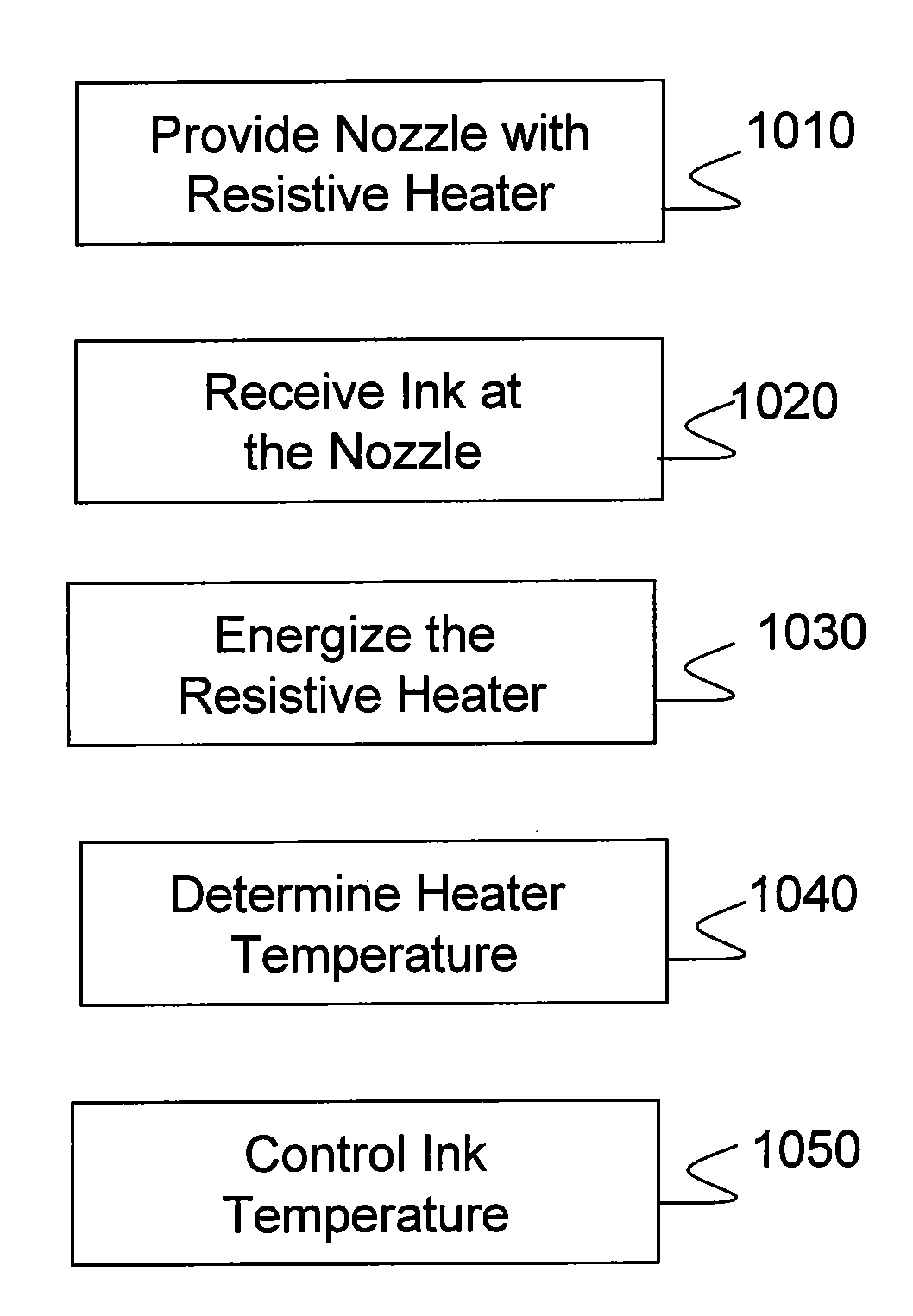
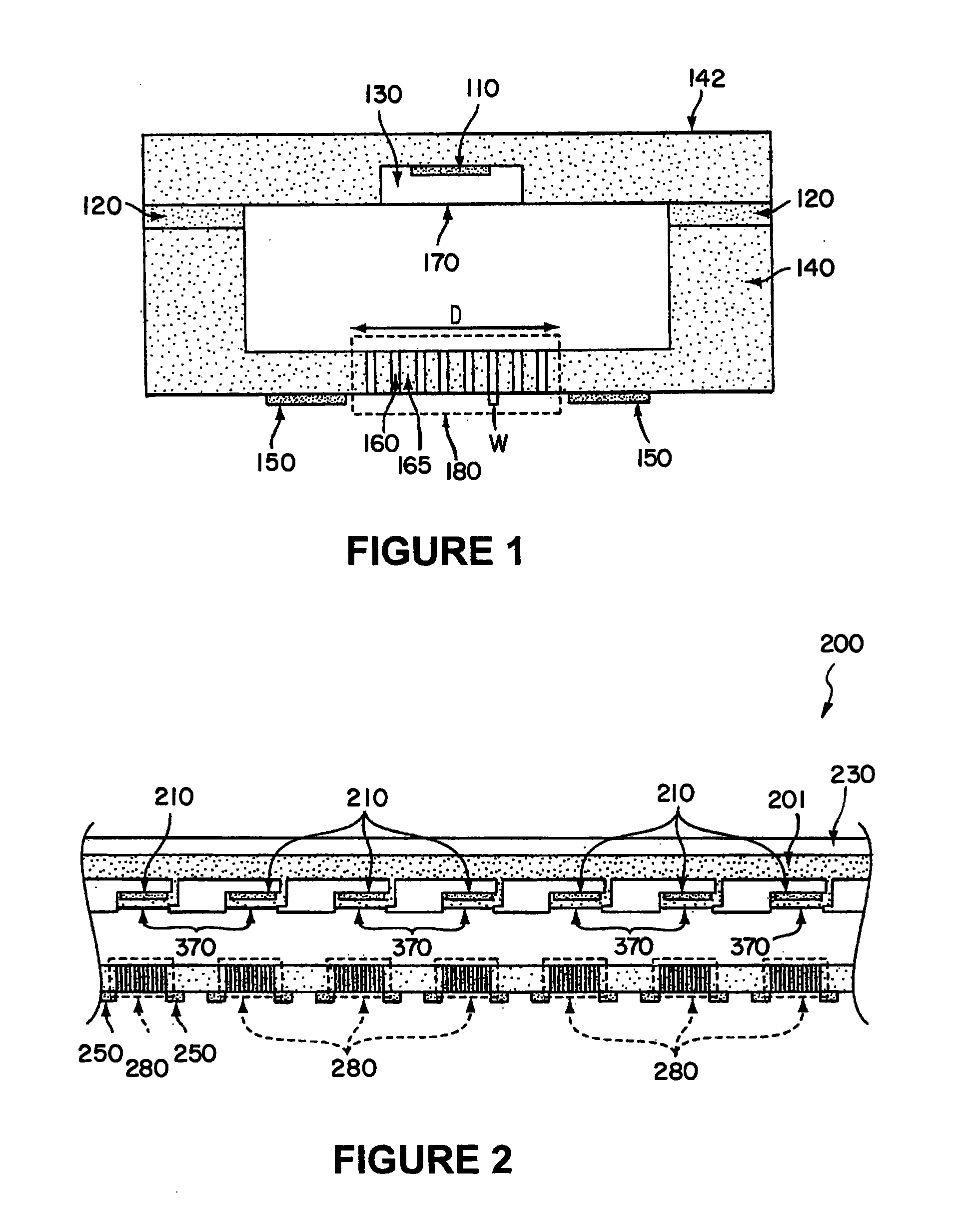
[0024]FIG. 1 is a schematic representation of an exemplary print-head having a thermal ink depositing mechanism according to one embodiment of the disclosure. The exemplary print-head of FIG. 1 includes chamber 130, orifice 170, nozzle 180, and micro-porous conduits 160. Chamber 130 receives ink in liquid form and communicates the ink from orifice 170 to discharge nozzle 180. The ink can comprise suspended or dissolved particles in a carrier liquid. These particles can comprise single molecules or atoms, or aggregations of molecules and / or atoms. The path between orifice 170 and discharge nozzle 180 defines a delivery path. In the embodiment of FIG. 1A, discharge nozzle 180 comprises conduits 160 separated by partitions 165. Conduits 160 may include micro-porous material therein. A surface of discharge nozzle 180 proximal to orifice 170 defines the inlet port to discharge nozzle 180 while the distal surface of discharge nozzle 180 defines the outlet port. A substrate (not shown) can...


PUM


Abstract

In an embodiment, the disclosure relates to a method and apparatus for fault monitoring and controlling operation of a discharge nozzle in a large array of discharge nozzles. An exemplary apparatus includes a thin, thermally conductive membrane, with an integrated thin-film electrical heater. When a fixed voltage is applied to the heater, and as the heater heats, the resistance of the heater will increase which will cause a concomitant decrease in the electrical current flowing through the heater. By measuring the resistance of the heater it can readily be determined whether the device is functioning properly.

Description

[0001]The instant application claims priority to Provisional Application No. 61 / 142,575, which was filed on Jan. 5, 2009, and to U.S. patent application Ser. No. 12 / 139,391, filed Jun. 13, 2008. The disclosures of both applications are incorporated herein in their entirety.BACKGROUND [0002]1. Field of the Invention[0003]The disclosure relates to a method and apparatus for sensing and controlling the temperature of an electrically resistive heater which may be integrated with a discharge nozzle of a print-head. More specifically, the disclosure relates to a novel controller for controlling temperature of a discharge nozzle. The discharge nozzle can be used for depositing substantially dry ink on a surface to be used for electronic applications.[0004]2. Description of Related Art[0005]The manufacture of organic light emitting devices (OLEDs) requires depositing one or more organic films on a substrate and coupling the top and bottom of the film stack to electrodes. The film thickness ...

Claims


Application Information

Patent Timeline
Patent Type & Authority Applications(United States)
IPC IPC(8): B41J29/38
CPCB41J2/14H01L51/0005B41J2/175H10K71/135B41J2/04588B41J2/17559B41J2/1433F04C15/0049B41J2/04598
Inventor MADIGAN, CONNOR F.SCHMIDT, MARTIN A.GASSEND, VALERIE
Owner MADIGAN CONNOR F
Why Eureka
Try Eureka