
Printer module including movable blade module and fixed blade module

a technology of printing module and fixed blade, which is applied in the field of printing module to achieve the effect of improving reliability

Active Publication Date: 2010-07-29
FUJITSU COMPONENENT LTD
View PDF8 Cites 29 Cited by
  • Summary
  • Abstract
  • Description
  • Claims
  • Application Information

AI Technical Summary

Benefits of technology

[0032]It is a general object of the present invention to provide a printer module and a printer apparatus that substantially eliminate one or more problems caused by the limitations and disadvantages of the related art.
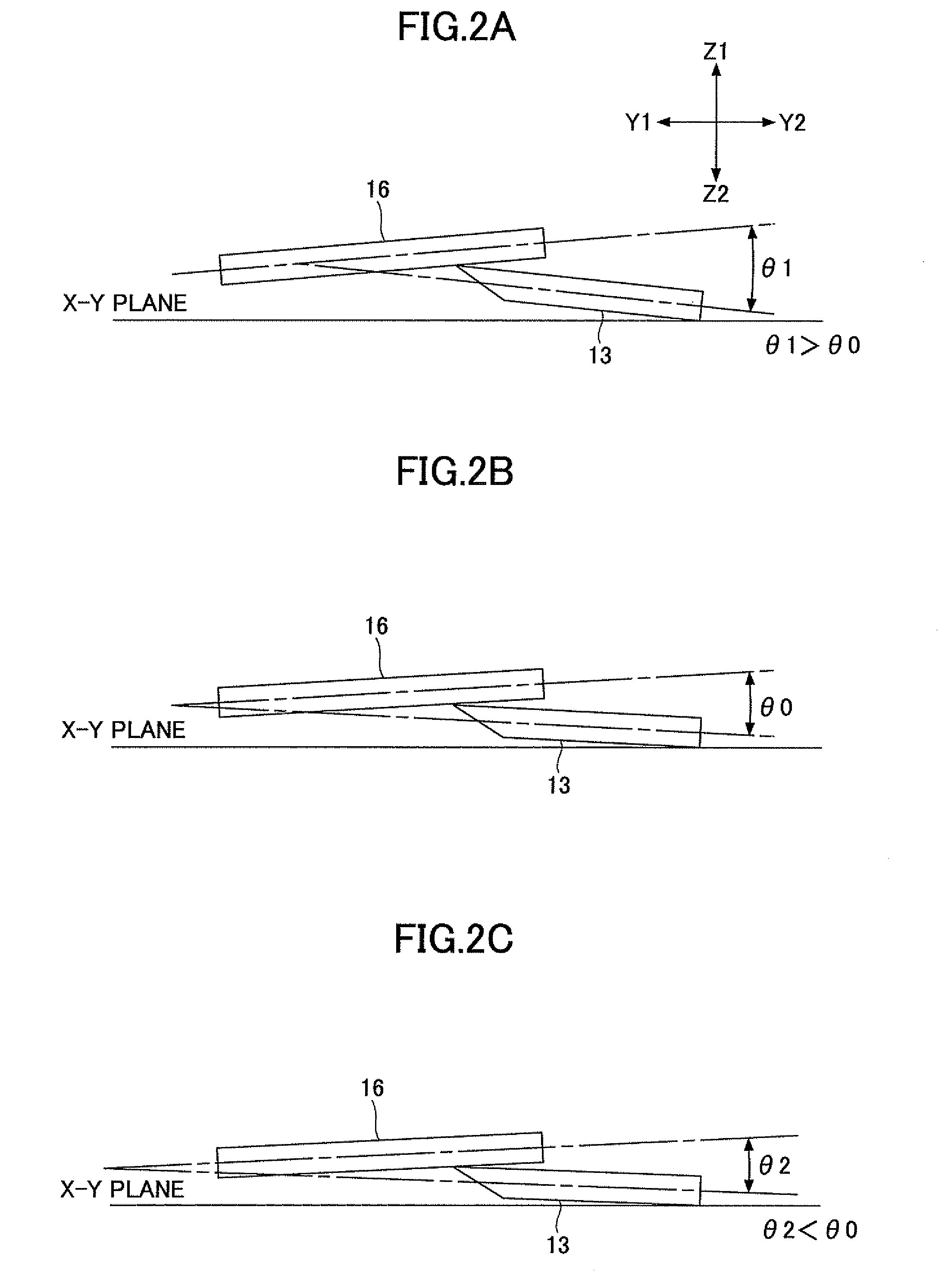
[0035]According to at least one embodiment, the movable blade module and the fixed blade module are configured such that an angle between the movable blade and the fixed blade becomes optimum upon joining the movable blade module to the fixed blade module. Further, the movable blade module is configured to be slightly movable when the movable blade module is mounted on the rotationally openable lid of the thermal printer apparatus. With this arrangement, the dimension error of the thermal printer apparatus, the positional error of the movable blade module upon being mounted, and the positional error of the fixed blade module upon being mounted do not affect the angle between the movable blade and the fixed blade in the cutter apparatus. Reliability can thus be improved.

Problems solved by technology

With this arrangement, the dimension error of the thermal printer apparatus, the positional error of the movable blade module upon being mounted, and the positional error of the fixed blade module upon being mounted do not affect the angle between the movable blade and the fixed blade in the cutter apparatus.

Method used


Image

  • Printer module including movable blade module and fixed blade module
  • Printer module including movable blade module and fixed blade module
  • Printer module including movable blade module and fixed blade module

Examples


first embodiment

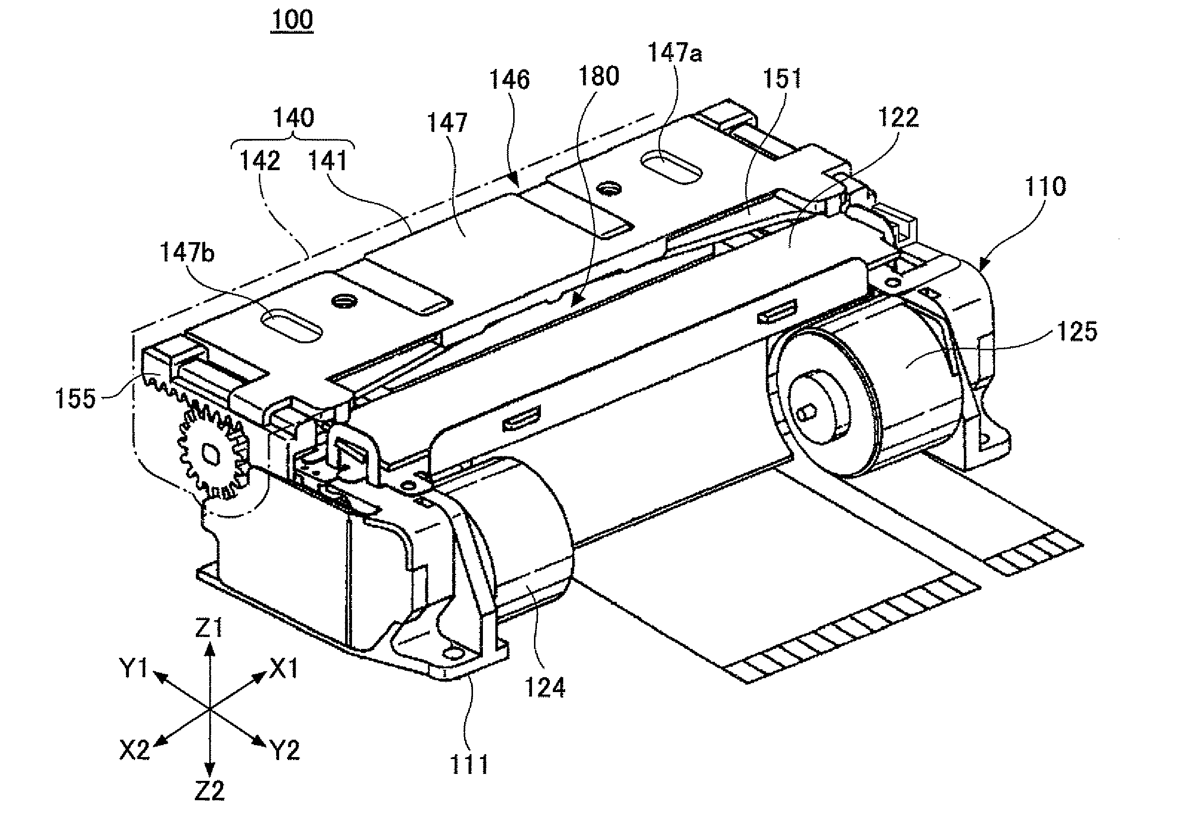
[0057]FIG. 6 is a perspective view of a thermal printer module 100 according to a first embodiment of the present invention. FIG. 7 is a side elevation view of the thermal printer module 100 illustrated in FIG. 6.

[0058]The thermal printer module 100 is configured such that a movable blade module 140 illustrated in FIG. 11 is joined in a separable manner to a fixed blade module 110 illustrated in FIG. 8 and FIG. 9. This configuration is used in a clamshell-type thermal printer apparatus.

[0059][Thermal Printer Module 100]

[0060]As illustrated in FIG. 8 and FIG. 9, the fixed blade module 110 includes a fixed blade module frame 111 that is a zinc die-cast component. The fixed blade module 110 further includes a fixed blade 122, a thermal head 123, a paper shifting pulse motor 124, a cutter-unit pulse motor 125, first and second speed reduction gear series 126 and 127, and a platen roller lock member 128, which are mounted on the fixed blade module frame 111.

[0061]The fixed blade module f...


PUM

PropertyMeasurementUnit
angleaaaaaaaaaa
widthaaaaaaaaaa
heightaaaaaaaaaa

Abstract

A printer module for use in a printer apparatus having a rotationally openable lid includes a fixed blade module having a fixed blade, a movable blade module having a movable blade and configured to be joined to the fixed blade module such that the movable blade and the fixed blade face each other, and a positioning unit configured to position the movable blade module relative to the fixed blade module such that an angle between the movable blade and the fixed blade becomes optimum upon joining the movable blade module to the fixed blade module, wherein the movable blade module is configured to be movable relative to the rotationally openable lid upon being mounted on the rotationally openable lid of the printer apparatus.

Description

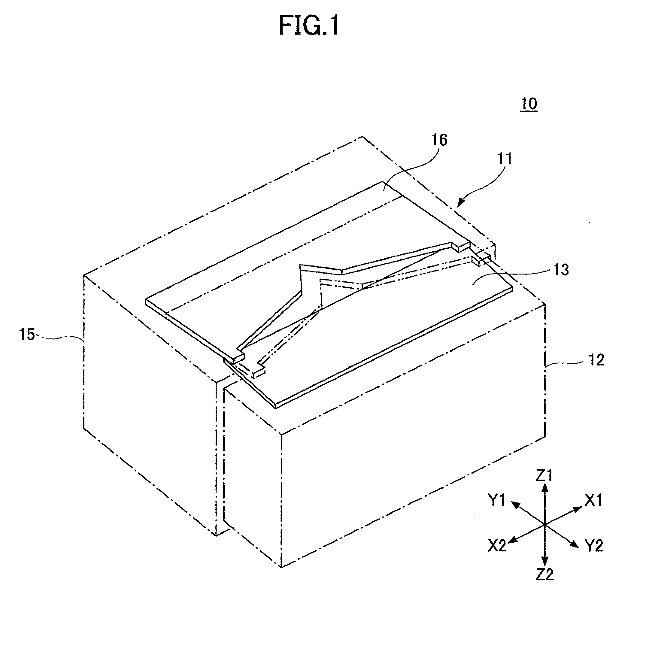
BACKGROUND OF THE INVENTION[0001]1. Field of the Invention[0002]The disclosures herein generally relate to printer modules, and particularly relate to a printer module for use in a clamshell-type printer apparatus wherein the printer module includes two modules that are combined to form a cutter unit having a movable blade and a fixed blade facing each other.[0003]2. Description of the Related Art[0004]A clamshell-type printer apparatus has an openable lid and a main body having respective modules attached thereto, which are joined together upon the rotational closing motion of the openable lid.[0005]A description will be given of a cutter unit having a movable blade and a fixed blade facing each other in a printer module for use in the clamshell-type printer apparatus.[0006]FIG. 1 is a drawing illustrating a typical cutter apparatus 11 of a thermal printer module 10 having a movable blade module 15 and a fixed blade module 12 joined together. X1-X2 represents the width direction of...

Claims


Application Information

Patent Timeline
Patent Type & Authority Applications(United States)
IPC IPC(8): B41J2/385
CPCB26D1/085B26D5/083B26D7/00B26D7/2614B41J29/02B26D2007/2685B41J2/325B41J11/70B26D7/2628Y10T83/0538Y10T83/391
Inventor TSUCHIYA, MASAHIROMORI, YUKIHIROWATANABE, SUMIO
Owner FUJITSU COMPONENENT LTD
Learn More