
Disk Drive Assembly Having Flexible Support for Flexible Printed Circuit Board

a technology of flexible printed circuit board and magnetic disk drive, which is applied in the direction of laminating printed circuit board, recording information storage, instruments, etc., can solve the problems of increasing the stabilization time of the read/write transducer, requiring costly materials, and eroding drive performance, so as to reduce the amount of flex of the flexible pcb attached

Inactive Publication Date: 2010-07-29
KK TOSHIBA
View PDF13 Cites 31 Cited by
  • Summary
  • Abstract
  • Description
  • Claims
  • Application Information

AI Technical Summary

Benefits of technology

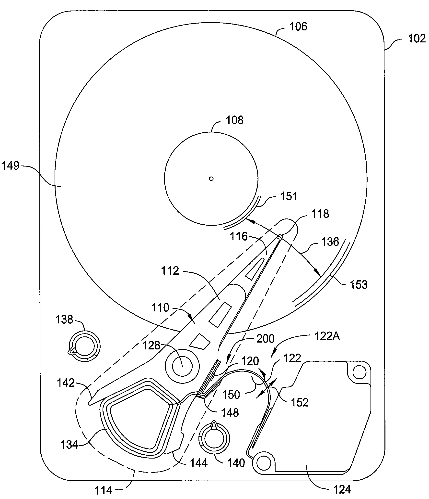
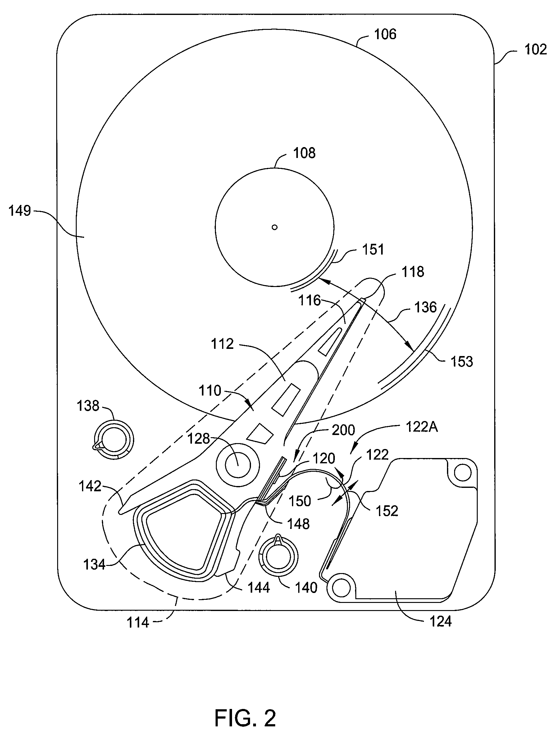
[0010]A disk drive assembly according a first embodiment includes a movable assembly having a mounting arm, a stationary electronics module, a flexible PCB electrically connecting the movable assembly to the stationary electronics module, and a flexible support having a first portion sandwiched between the flexible PCB and the mounting arm and a second portion attached to the flexible PCB that extends past the end of the mounting arm, wherein during movement of the movable assembly, the second portion of the flexible support flexes and reduces the amount of flex of the flexible PCB attached thereto.
[0011]A disk drive assembly according a second embodiment includes a movable assembly having a mounting arm, a stationary electronics module, a flexible PCB electrically connecting the movable assembly to the stationary electronics module, and a flexible support sandwiched between the flexible PCB and the mounting arm and attached to the flexible PCB through an adhesive layer that damps vibrations in the flexible PCB.

Problems solved by technology

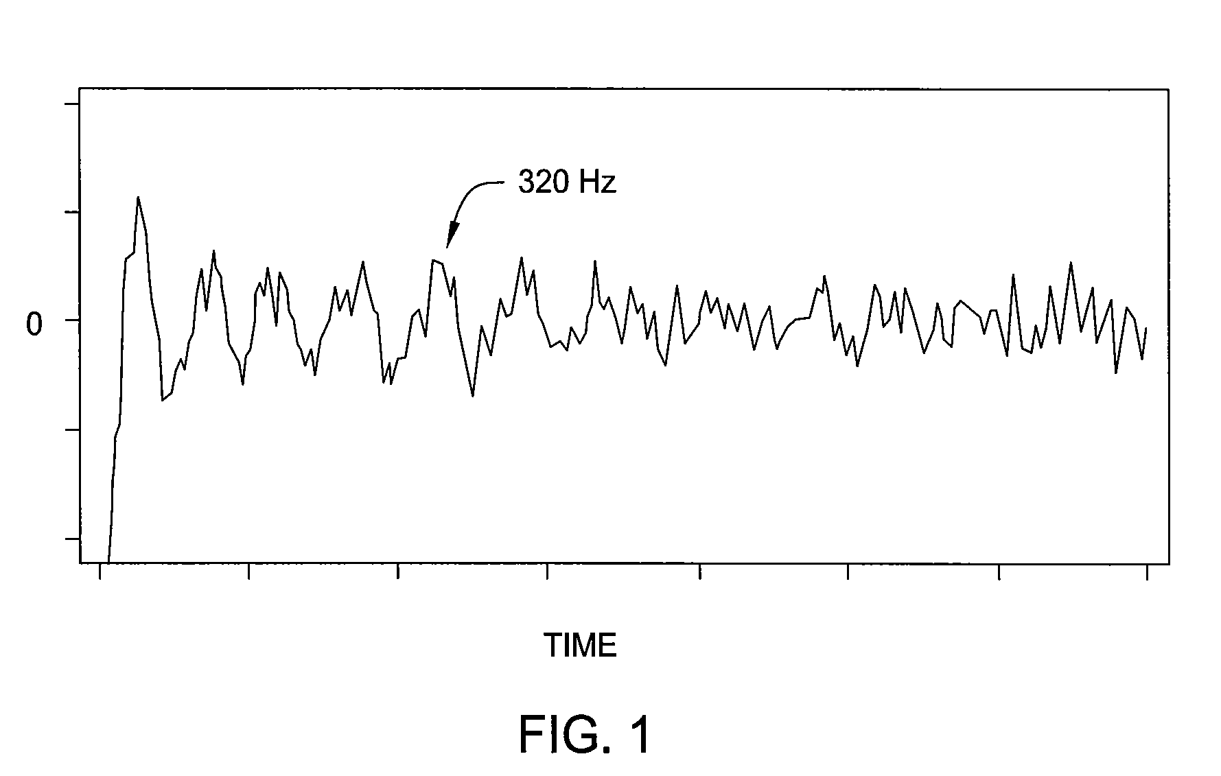
In addition, the acceleration and deceleration of the positioning actuator when moving the read / write transducer to a selected track further excites low-frequency resonances in the flex PCB, increasing stabilization time of the read / write transducer and eroding drive performance.
However, such solutions involve designs solutions that are complex, difficult to manufacture, and / or require costly materials.

Method used


Image

  • Disk Drive Assembly Having Flexible Support for Flexible Printed Circuit Board
  • Disk Drive Assembly Having Flexible Support for Flexible Printed Circuit Board
  • Disk Drive Assembly Having Flexible Support for Flexible Printed Circuit Board

Examples


Embodiment Construction

[0026]Embodiments of the invention contemplate a vibration-damping system for a disk drive that reduces vibration of a flexible printed circuit board (PCB) of the disk drive. The vibration-damping system includes a flexible stiffener attached to a flexible PCB via a viscoelastic adhesive layer to form a layered structure disposed at an attachment point of the connecting loop of the flexible PCB. The respective thicknesses of the flexible PCB, the viscoelastic adhesive layer, and the flexible stiffener provide the layered structure with an overall stiffness that maintains the flexible PCB oriented near an optimal exit angle from the flexible PCB attachment point throughout the range of motion of the flexible PCB, thereby reducing mechanical coupling between the flexible PCB and the actuator assembly of the disk drive. In addition, the viscoelastic adhesive layer damps resonances present in the flexible PCB. The damping treatment can be easily applied to the flexible PCB without signi...


PUM


Abstract

A disk drive assembly includes a movable assembly having a mounting arm, a stationary electronics module, a flexible printed circuit board (PCB) electrically connecting the movable assembly to the stationary electronics module, and a flexible support sandwiched between the flexible PCB and the mounting arm. The flexible support is attached to the mounting arm and the flexible PCB, and extends past the mounting arm of the movable assembly. The flexible support is flexible enough to flex with the flexible PCB but has sufficient rigidity so that an exit point and an exit angle of the flexible PCB can vary during movement of the movable assembly. In addition, the flexible PCB is attached to the flexible support through an adhesive layer that damps vibrations in the flexible PCB.

Description

BACKGROUND OF THE INVENTION[0001]1. Field of the Invention[0002]Embodiments of the present invention relate generally to magnetic disk drives and, more particularly, to a magnetic disk drive assembly having a flexible support for a flexible printed circuit board.[0003]2. Description of the Related Art[0004]Magnetic disk drives are commonly used in computer systems since such drives can inexpensively store large quantities of non-volatile data for quick access. Magnetic disk drives generally include one or more rotatable magnetic media disks having concentric data tracks defined for storing data, a magnetic read / write transducer for reading data from and / or writing data to the various data tracks, a slider mechanism for supporting the read / write transducer in close proximity to the data tracks, and a rotatable positioning actuator coupled to the transducer / slider combination for moving the read / write transducer across the media to the desired data track and maintaining the transducer...

Claims


Application Information

Patent Timeline
IPC IPC(8): G11B5/48
CPCG11B5/4846H05K2201/2009H05K3/0058H05K1/0281
Inventor CASTAGNA, JOSEPH T.
Owner KK TOSHIBA
Learn More